


ACCULINK 317x E1 DSU/CSU
3-2 December 1996 3170-A2-GB20-20
Overview
This chapter contains information for operating your
E1 DSU/CSU. It includes a description of the front panel
and sample procedures for configuring the E1 DSU/CSU.
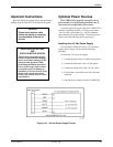
Using the Front Panel
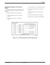
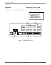
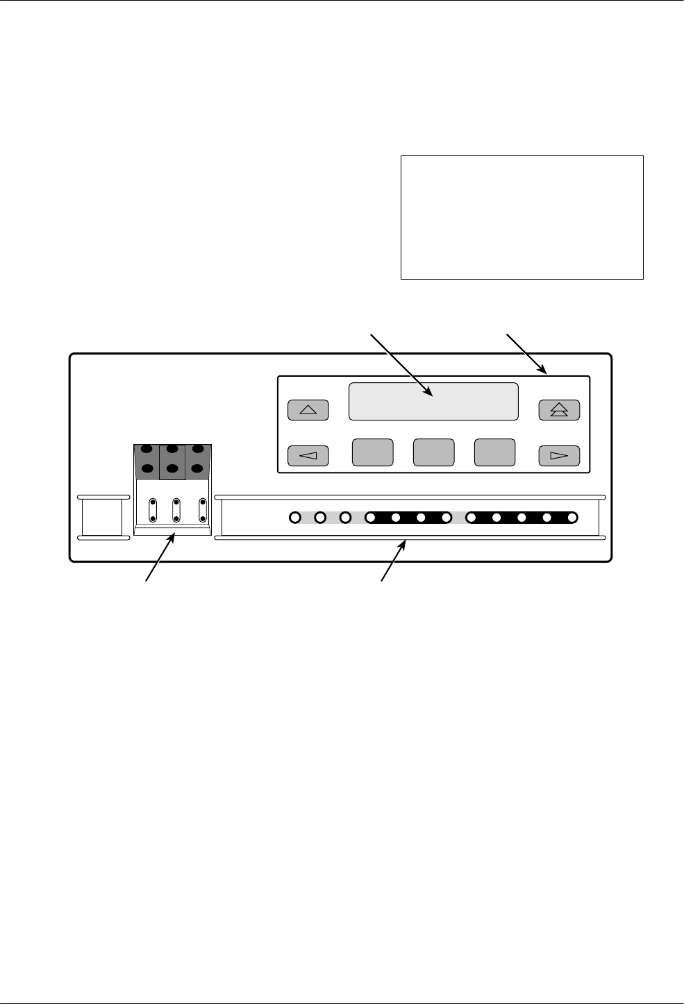
The E1 DSU/CSU front panel (Figure 3-1) consists of
an LCD, a keypad, test jacks, and 12 LEDs.
NOTE
You can display a graphical
representation of the E1
DSU/CSU front panel on an
attached PC (see Appendix G,
Front Panel Emulation
).
F1 F2 F3
OK
FAIL TEST SIG OOF ALRM
NETWORK RXD
EER SIG ALRM PDVOOF BPV
LCD
ACCULINK
In
Out
In
Out
In
Out
NET
NET
MON
EQPT
MON
DTR TXD CTS RTS
496-14539-0
3
KEYPAD
TEST JACKS LEDs
Figure 3-1. E1 DSU/CSU Front Panel