


ACCULINK 317x E1 DSU/CSU
D-14 December 1996 3170-A2-GB20-20
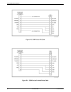
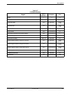
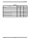
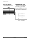
Power Input Connector
The input power connector leads are shown in
Table D-9.
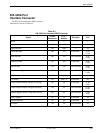
Table D-9
DC Power Connector
Signal
Pin Number
–48 Vdc Return
1, 2
–48 Vdc A 6
–48 Vdc B 5
+24 Vdc 5
+24 Vdc Return 4
Chassis Ground 3
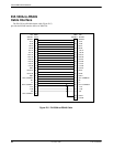
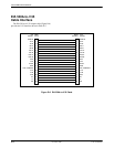
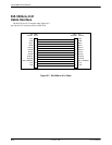
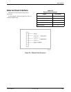
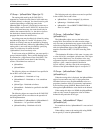
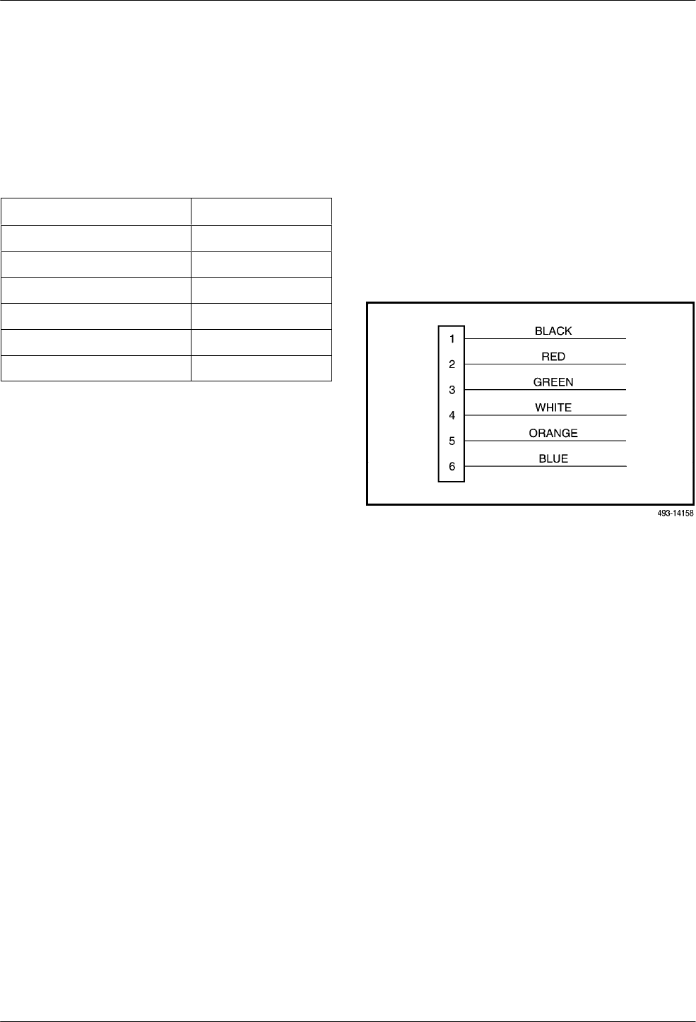
Optional DC Power Cable
The power cable is a 14.5-foot, 18 A
WG stranded
cable. The connector is terminated at one end with a
6-position connector. The other end of the cable is
terminated with a bare wire that should be connected to a
dc power source. Figure D-8 shows the wire colors. The
power source can be either a single source of +24 Vdc or
up to two sources of –48 Vdc (A and B). Y
ou cannot
connect +24 Vdc and –
48 Vdc to the same unit. See the
installation instructions in Chapter 2,
Installation.
Figure D-8. DC Power Cable