


ACCULINK 317x E1 DSU/CSU
2-8 December 1996 3170-A2-GB20-20
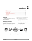
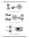
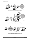
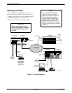
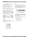
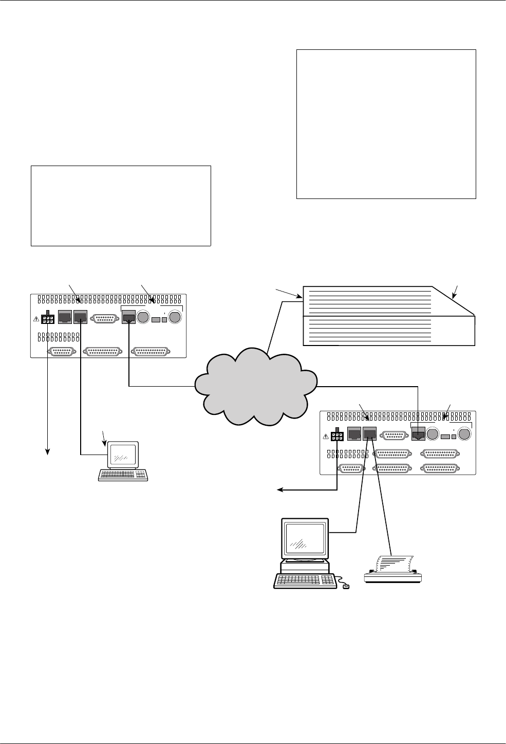
Cabling Examples
The E1 DSU/CSU is supplied with an ac power
module. You must provide the DTE and network cables.
Optional cables that you can order from the company
are described in Appendix D,
Pin Assignments
.
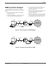
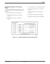
Figure 2-13 illustrates some cabling examples.
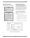
CAUTION
Disconnect the power cable
before connecting or removing
any data cables at the rear of
the unit.
NOTE
The 120Ω/75Ω switch selects
either the 120 ohm balanced
network interface or the 75 ohm
unbalanced network interface.
The RX SHIELD switch selects
either an “open” or “earth” shield
connection for the 75 ohm RX
interface. (This switch must be set
to “open” when using the 120 ohm
interface.)
POWER
AUX
PORT
COM
PORT
DTE
PORT 1 PORT 2CLOCK IN
120Ω
75Ω
75Ω
120Ω
RX SHIELD
OPEN
EARTH
RX
75Ω
TX
NETWORK
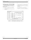
CAUTION: AUX PORT OR COM PORT MUST NOT BE
CONNECTED TO PSTN OR E1 NETWORK
POWER
AUX
PORT
COM
PORT
DTE
PORT 3 PORT 4
PORT 1 PORT 2CLOCK IN
120Ω
75Ω
75Ω
120Ω
RX SHIELD
OPEN
EARTH
RX
75Ω
TX
NETWORK
CAUTION: AUX PORT OR COM PORT MUST NOT BE
CONNECTED TO PSTN OR E1 NETWORK
495-14673-0
1
NETWORK
TO AC
POWER
MODULE
TO DC
POWER
(OPTIONAL)
3100-F1-550
3100-F1-540
FRONT
PANEL
DSU/CSU
DSU/CSU
DSU/CSU
SERIAL
PORT
COM PORT
NETWORK
COM PORT
NETWORK
3100 SERIES
FRONT PANEL
EMULATION
SOFTWARE,
3100-C1-010
NOTE:
3100-F1-520
NETWORK
SNMP
MANAGER
OR
Figure 2-13. Cabling Examples