


Operation
3-273170-A2-GB20-20 December 1996
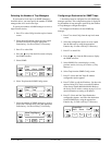
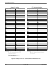
Displaying DS0 Channel Assignments
Use
the Display command (in the Channel
Configuration branch) to view how the DS0 channels are
currently allocated.
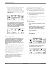
Line 1 of the display shows the 31 channels of the
selected interface. Pressing
or
scrolls the next
three channels onto the LCD. Line 2 displays what is
allocated to the DS0 channel listed in Line 1. Symbols
used in the display are shown in T
able 3-5.
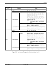
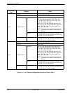
Table 3-5
Display Channel Symbols
Symbol
Meaning
– The DS0 channel is not allocated.
Prt
n
The DS0 channel is allocated to Port
n
,
where
n
is 1, 2, 3, or 4.
N
n
The DS0 channel is allocated to the
Network E1 interface DS0 channel
n
,
where
n
can be any number from 1
through 31.
D
n
The DS0 channel is allocated to the DTE
Drop/Insert interface DS0 channel
n
,
where
n
can be any number from 1
through 31.
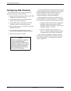
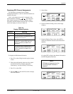
T
o display the DS0 channel allocation,
1. Press F3 to select Cnfig from the top-level menu
screen.
2. Select the configuration option set to be copied
into the Edit area by using the appropriate
Function key
. Use the scroll keys, if necessary
.
3. Press F1 to select Edit.
4.
Press the
key from the Edit screen to display
the Chan selection.
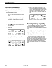
5.
Select Chan.
F1
Edit:
Port NET Chan
F2
F3
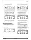
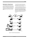
6.
From the Channel Config screen, select Dsply
(display).
F1
Channel Config:
Dsply Clear DTE
F2
F3
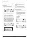
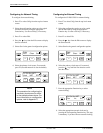
7. From
the Display Chan screen, select NET to
display the channels allocated to the Network E1
interface.
F1
Display Chan:
NET DTE Ports
F2
F3
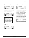
Or,
select DTE to display the channels allocated to
the DTE Drop/Insert interface.
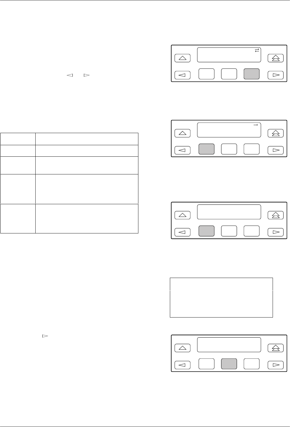
NOTE
DTE does not appear when the
DTE Drop/Insert interface is
disabled.
F1
Display Chan:
NET DTE Ports
F2
F3