8700-A2-GB20-40 May 2002
C-1
C
Connector Pin Assignments
Overview
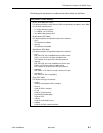
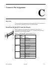
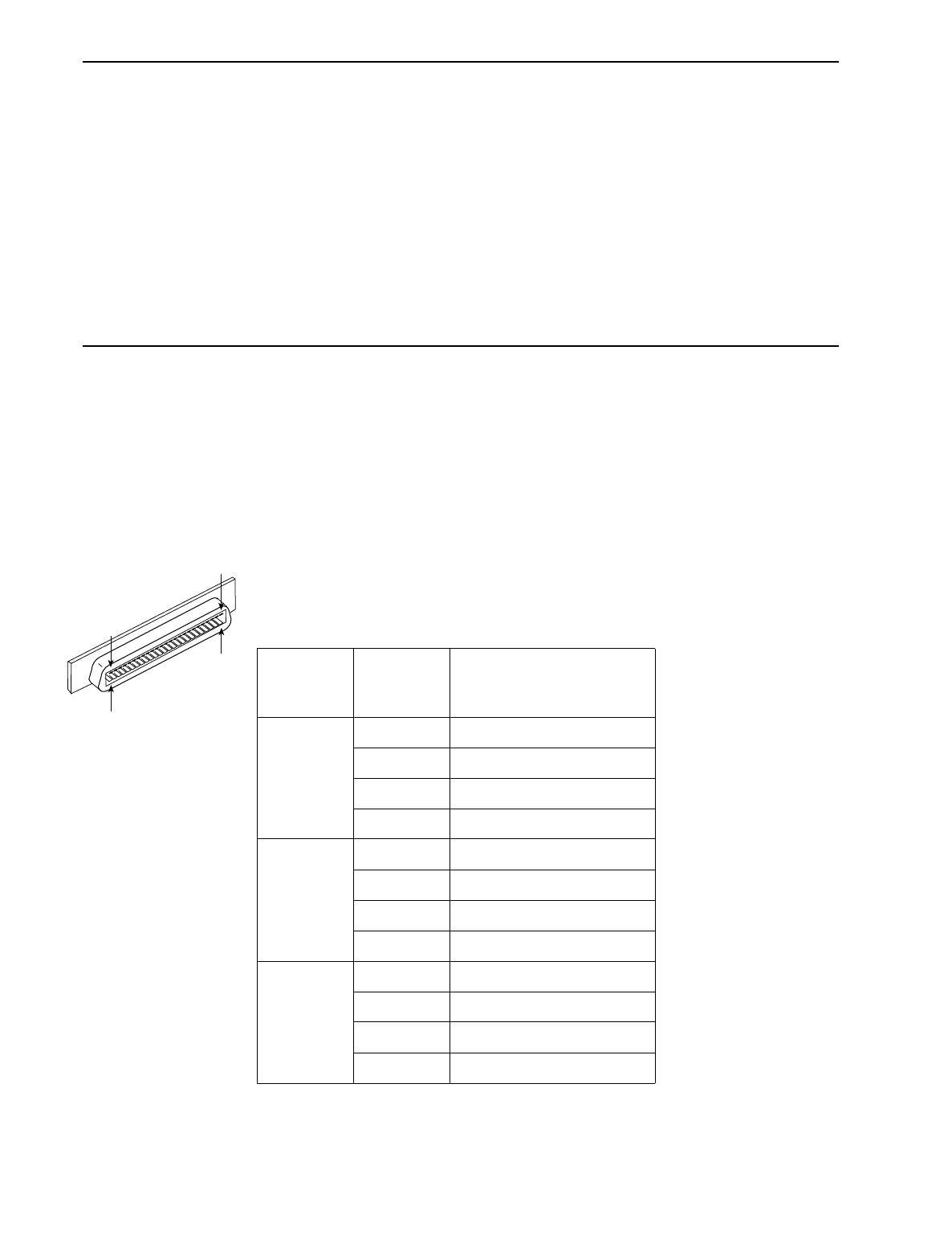
This section lists the pin assignments for the front panel 50-pin DTE connector and
the 50-pin Telco connectors on the rear of the DSLAM chassis.
Front Panel 50-pin DTE Connector Pinouts
The DTE connectors on the termination unit provide the 4-wire DSX-1 or
G.703 interface from each DSL port to the DTE. The following table lists the pin
assignments for each of these interfaces.
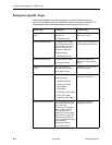
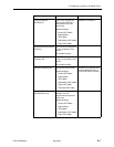
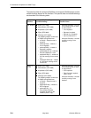
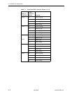
Table C-1. Front Panel DTE Connector Pinouts (1 of 2)
DSX-1 or
G.703 Port
50-Pin
Connector
Pinout Function
Port 1 27 Data Out (Ring)
2Data Out (Tip)
26 Data In (Tip)
1 Data In (Ring)
Port 2 30 Data Out (Ring)
5Data Out (Tip)
29 Data In (Tip)
4 Data In (Ring)
Port 3 33 Data Out (Ring)
8Data Out (Tip)
32 Data In (Tip)
7 Data In (Ring)
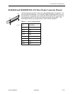
26
97-15323
50
1
25


