9. Transferring Firmware and Configurations Using TFTP
8700-A2-GB20-40 May 2002
9-5
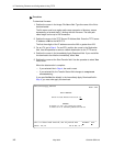
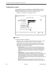
2. Position the cursor in the TFTP Server IP Address field. Enter the TFTP server
IP address or
M1
for the MCP FFS.
The first three digits of the IP address cannot be 000 or greater than 223.
3. Position the cursor in the TFTP Transfer Direction field. Use the spacebar to
select Download from Server or Upload to Server.
4. For an LTU, go to Step 5. For an NTU, position the cursor in the Destination
field. Use the spacebar to select a network destination for the TFTP server.
Select DSL if the TFTP server destination is the DSL link port or IMC (Internal
Management Channel) if the TFTP destination is the Management port of the
MCC card.
5. Position the cursor at the Start Transfer field. Use the spacebar to select Yes.
Press Enter.
When the data transfer is complete, the Transfer Status field changes to
Completed successfully
.
6. Position the cursor at the
Activate new configuration?
prompt and
select
Yes
to activate a new downloaded configuration. Press Enter.
NOTE:
The following options are not changed:
— DSL Mode and Telnet Session configuration options
— Peer IP address
You must change these settings with the appropriate configuration menus
after the new configuration is activated. See Table A-7, System Options, and
Table A-12, Telnet Session Options, in Appendix A,
Configuration Options
.


