List of Tables Intel® SHG2 DP Server Board Technical Product Specification
Intel Order Number C11343-001 Revision 1.0
x
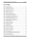
Table 31. Recovery BIOS POST Codes........................................................................44
Table 32. POST Error Messages and Codes................................................................45
Table 33. SHG2 Configuration Jumper Options............................................................49
Table 34. SHG2 Baseboard Connectors.......................................................................50
Table 35. Main Power Connector..................................................................................51
Table 36. +12V Power Connector .................................................................................51
Table 37. Power Connector for I
2
C* Bus .......................................................................52
Table 38. 68-pin SCSI Connector Pin-out .....................................................................52
Table 39. Legacy 34-pin Floppy Connector Pin-out ......................................................53
Table 40. Primary/Secondary IDE 40-pin Connector Pinout .........................................54
Table 41. AT Front Panel Header Pinout ......................................................................55
Table 42. Intel
®
Xeon™ Processor Connector Pinout ...................................................56
Table 43. ICMB Connector Pin-out................................................................................60
Table 44. IPMB Connector Pinout.................................................................................60
Table 45. SC5200 Fan Implementation........................................................................63
Table 46. Fan Connector Pinout ...................................................................................63
Table 47. I/O Panel Connectors ....................................................................................65
Table 48. USB Connector .............................................................................................65
Table 49. Internal USB Connector.................................................................................65
Table 50. Mouse and Keyboard Ports...........................................................................66
Table 51. Serial A Port Connector.................................................................................66
Table 52. Serial B Port Header: COM2/EMP ................................................................67
Table 53. Parallel Port Connector .................................................................................67
Table 54. Video Connector............................................................................................68
Table 55. Ethernet Connectors .....................................................................................68
Table 56. LAN1 10/100 LED Schemes .........................................................................69
Table 57. LAN2 10/100/1000 LED Schemes ................................................................69
Table 58. Baseboard Connector Manufacturer Part Numbers ......................................70
Table 59. Absolute Maximum Electrical and Thermal Specifications ............................72
Table 60. Thermal Specification for Key Components ..................................................72
Table 61. Airflow Specification for Key Components.....................................................73
Table 62. SHG2 Power Budget .....................................................................................73
Table 63. SHG2 DC Power Supply Voltage Specification.............................................74


