Intel® SHG2 DP Server Board Technical Product Specification Connections
Revision 1.0 Intel Order Number C11343-001
61
8.9 Baseboard Fan Connectors
(FAN1 through FAN8)
SHG2 provides eight 3-pin, shrouded, and keyed fan connectors. Each fan can be equipped
with a sensor that indicates whether the fan is operating. Two fan connectors are for processor
cooling fans, two fan connectors are for back of chassis, and four connectors on the baseboard
attach to chassis fans equipped with a sensor that indicates whether the fan is operating. The
chassis fans can also be turned on and off from the BMC. The sensor pins for all of these fans
are routed to the BMC for failure monitoring
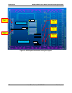
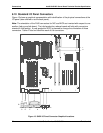
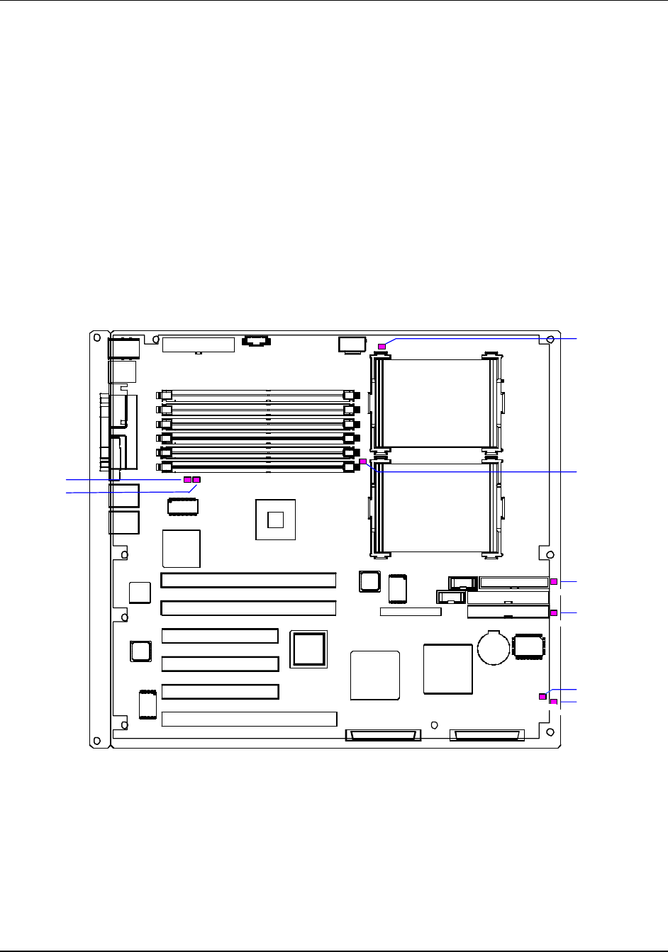
Figure 11 shows the fan connector locations on the SHG2 server board, and indicates the
corresponding types of fan.
1
FAN4, CN46
FAN3, CN41
FAN6, CN36
FAN5, CN28
FAN2, CN22
FAN1, CN23
CPU1 Fan, CN1
CPU2 Fan, CN18
Figure 11. SHG2 Board Fan Connector Locations


