Intel® SHG2 DP Server Board Technical Product Specification Connections
Revision 1.0 Intel Order Number C11343-001
65
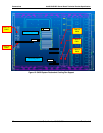
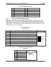
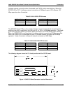
Table 47. I/O Panel Connectors
Key Connector Name Key Connector Name
A USB connector, port C F Serial A (COM1) connector
B USB connector, port B G Parallel Port connector
C USB connector, port A H VGA Video connector
K USB connector, port D I NIC2 connector (10/100/1000)
D Mouse (Keyboard) connector J NIC1 connector (10/100)
E Keyboard (Mouse) connector L Serial B (COM2/EMP) connector
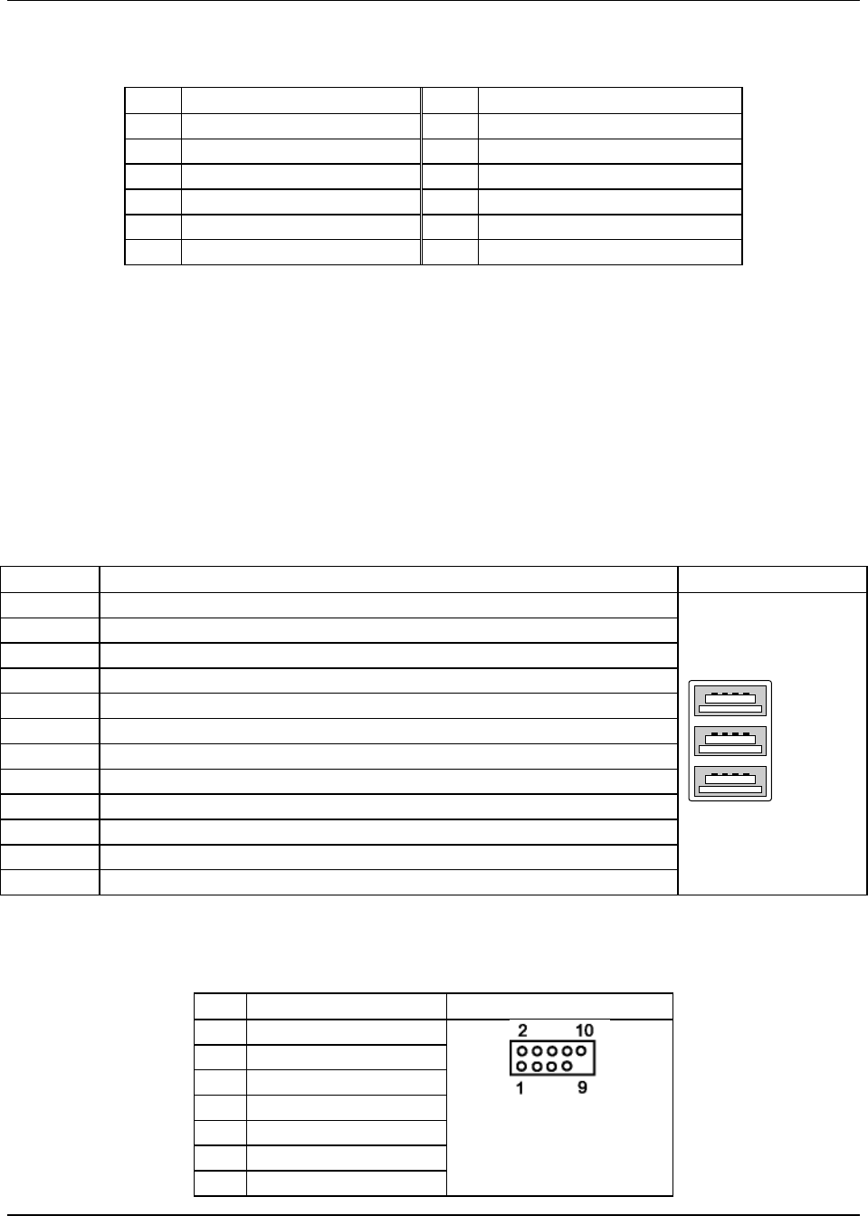
8.10.1 Universal Serial Bus (USB) Interface
[Key A, B & C] The baseboard provides three stacked USB ports (Port 2 on top, Port 0 in
middle, Port 1 on bottom). The built-in USB ports permit the direct connection of three USB
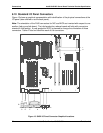
peripherals without an external hub. A fourth USB port [Key K] is available through an on-board
header (CN33). If more devices are required, an external hub can be connected to either the
back-panel ports or the on-board header.
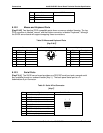
Table 48. USB Connector
[Key-A, B & C]
Pin Signal USB Connector
1, Port A USBP1_VCC (Fused VCC, +5V with over current monitor of port 0, 1, and 2)
2, Port A USB_P1_N (Differential data line paired with USB_P1_P)
3, Port A USB_P1_P (Differential data line paired with USB_P1_N)
4, Port A USBP1_GND
5, Port B USBP0_VCC (Fused VCC, +5V with over current monitor of port 0, 1, and 2)
6, Port B USB_P0_N (Differential data line paired with USB_P0_P)
7, Port B USB_P0_P (Differential data line paired with USB_P0_N)
8, Port B USBP0_GND
9, Port C USBP2_VCC (Fused VCC, +5V with over current monitor of port 0, 1, and 2)
10, Port C USB_P2_N (Differential data line paired with USB_P2_P)
11, Port C USB_P2_P (Differential data line paired with USB_P2_N)
12, Port C USBP2_GND
Port A
Port B
Port C
Table 49. Internal USB Connector
USB [Key-K]
Pin Name Internal USB Connector
1 (No Connect)
2 USBP3_VCC
3 (No Connect)
4 USB_P3_N
5 (No Connect)
6 USB_P3_P
7 (No Connect)


