CM9740-CC1 | 19
6.1.6 Single-Node Hot Switch Configurations
Refer back to Figure 7 and note the information in the lower right-hand corner of the
diagnostic screen. Specifically, note the A OFF phrase. This means “Asynchronous
OFF,” which means the CC1 is not part of a
hot switch
configuration.
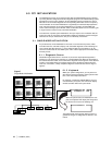
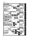
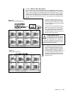
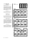
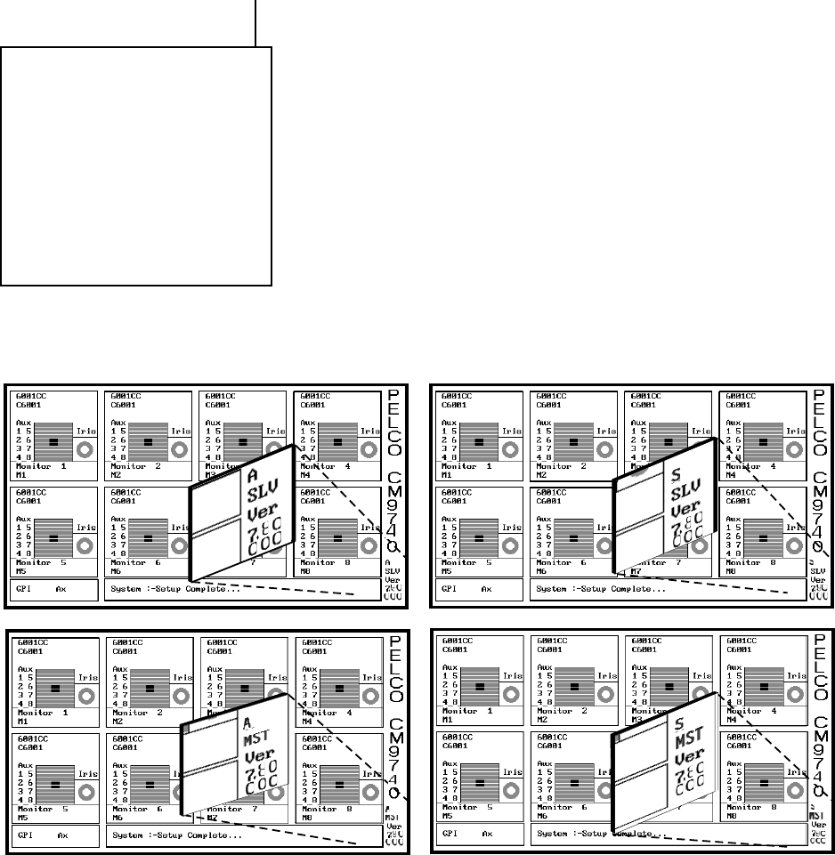
If, however, the CC1 is part of a hot switch configuration, that portion of the diagnostic
screen represents the state of the CC1 being visually sampled at the time. This, in
turn, depends on the switch settings on the processor board located in the hot switch
interface. You might see any one of the four different diagnostic screens displayed in
Figure 12 at the conclusion of CC1 initialization. However, this would be the only area
of difference in the diagnostic display to indicate that the boot up initialization process
had been successful. MGR program displays for hot switch configurations are the
same as those already discussed.
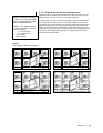
Figure 12
Single-Node Hot Switch Configurations
NOTE:
The diagnostic monitor and
the external PC containing the MGR
program are attached to the hot switch
interface CM9760-CCS-PNL.
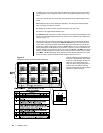
NOTE:
In the diagrams below, the
hot switch terminology references
mean the following:
A = Asynchronous
S = Synchronous
SLV = Slave
MST = Master


