22 | C1508M-A (02/01)
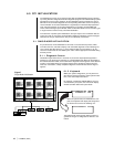
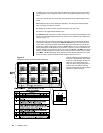
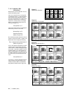
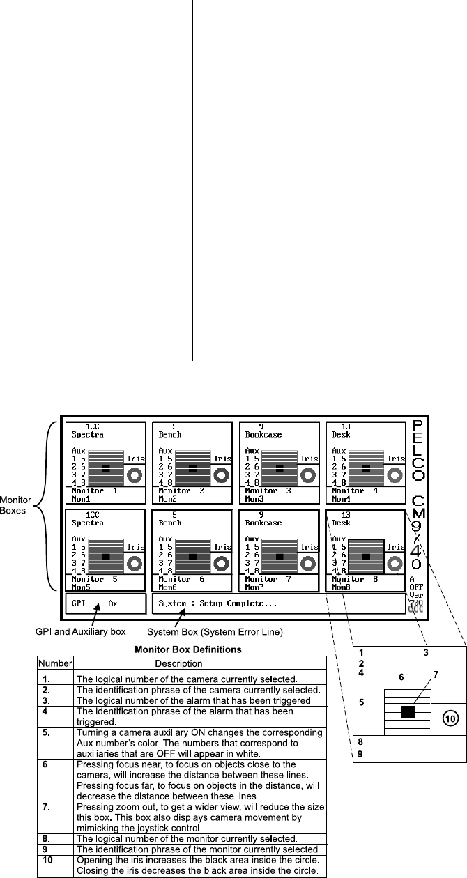
In addition to the area of the screen where the System box appears, there are two other ar-
eas of significance on the diagnostic screen. Refer to the sample diagnostic screen in Fig-
ure 14.
First, there is the GPI and Ax (short for Aux) box located in the lower left-hand portion of the
screen.
GPI displays the GPI currently selected (if applicable). The GPI number will be updated
when an auxiliary command is executed.
Ax displays the auxiliary currently selected and whether it is ON or OFF.
Second, there are eight identical Monitor boxes.
Each Monitor box represents a monitor and the camera currently being displayed on that
monitor. The information displayed within each monitor box is detailed by the numbered ref-
erences in Figure 14.
We might point out some other miscellaneous information areas associated with the diag-
nostic screen. Below the vertically placed PELCO CM9740 logo, on the right side of the
screen, there is a boxed area within which information is given about the CC1 and its rela-
tionship to hot switch configurations. The term A OFF means your CC1 is not part of a hot
switch configuration. The A stands for asynchronous. If the CC1 is part of a hot switch con-
figuration operating in asynchronous mode, then it may read A SLV or A MST. The normal
state for hot switch operation is, however, the synchronous mode, in which case you would
see S MST or S SLV depending on hot switch parameters. Directly below this, the current
version level of the system executable is listed using the format Ver xxx xxx.
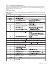
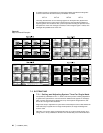
That concludes the general description of
the layout of the diagnostic screen. Next,
we’ll look at a few examples of what you
might see on the monitor boxes and
show you how to change monitor box al-
location. Then, we shall list some key-
board commands that are used to gather
specifics on system operation.
Figure 14
Diagnostic Screen and Monitor Box Geometry


