8 | C1508M-A (02/01)
4.0 INTRODUCTION TO THE CC1
4.1 DESCRIPTION
The CM9740-CC1 Controller is the main component and central operating hub of the Sys-
tem 9740. All components of the system connect to and communicate with the Controller
via the ports located on the rear of the unit.
The CM9740-CC1 Controller mounts in a standard 19-inch (48.26 cm) rack space.
NOTE:
The internal cards are manu-
factured or supplied by Pelco and con-
tain no user-serviceable parts. Other
than jumper settings or card replace-
ment, any attempt to repair or modify
the internal components of the
CM9740-CC1 will void any applicable
warranties.
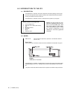
Default Hardware Configuration
a. 3.5-inch Floppy Drive
b. Solid-state, non-volatile, flash memory
c. CPU
d. Mounting hardware
e. Keyboard
f. Mouse
g. 2 SerCom cards
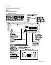
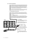
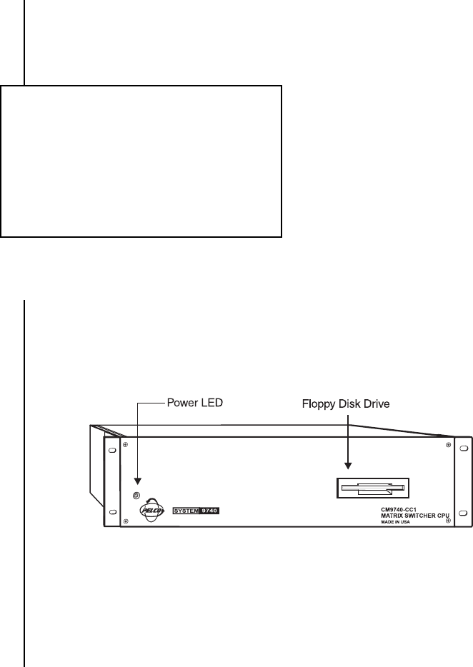
Figure 1
CM9740-CC1 Front View
4.2 MODEL
CM9740-CC1 CPU controller and processor, operates on 120-240 VAC, 50/60 Hz.
(CE, UL, cUL)
Front View
The front area of the controller consists of the items identified in the illustration in Figure 1:
The CM9740-CC1 Controller is equipped with an internal power supply that provides all the
operating voltages for the unit. * Cooling for the processor is provided by a CPU-mounted
fan.
* The power socket outlet shall be installed near the equipment and shall be easily accessable.


