


2 – General Description
Chassis Controls and LEDs
2-2 59042-06 A
0
2.1
Chassis Controls and LEDs
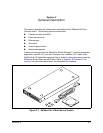
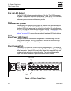
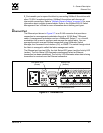
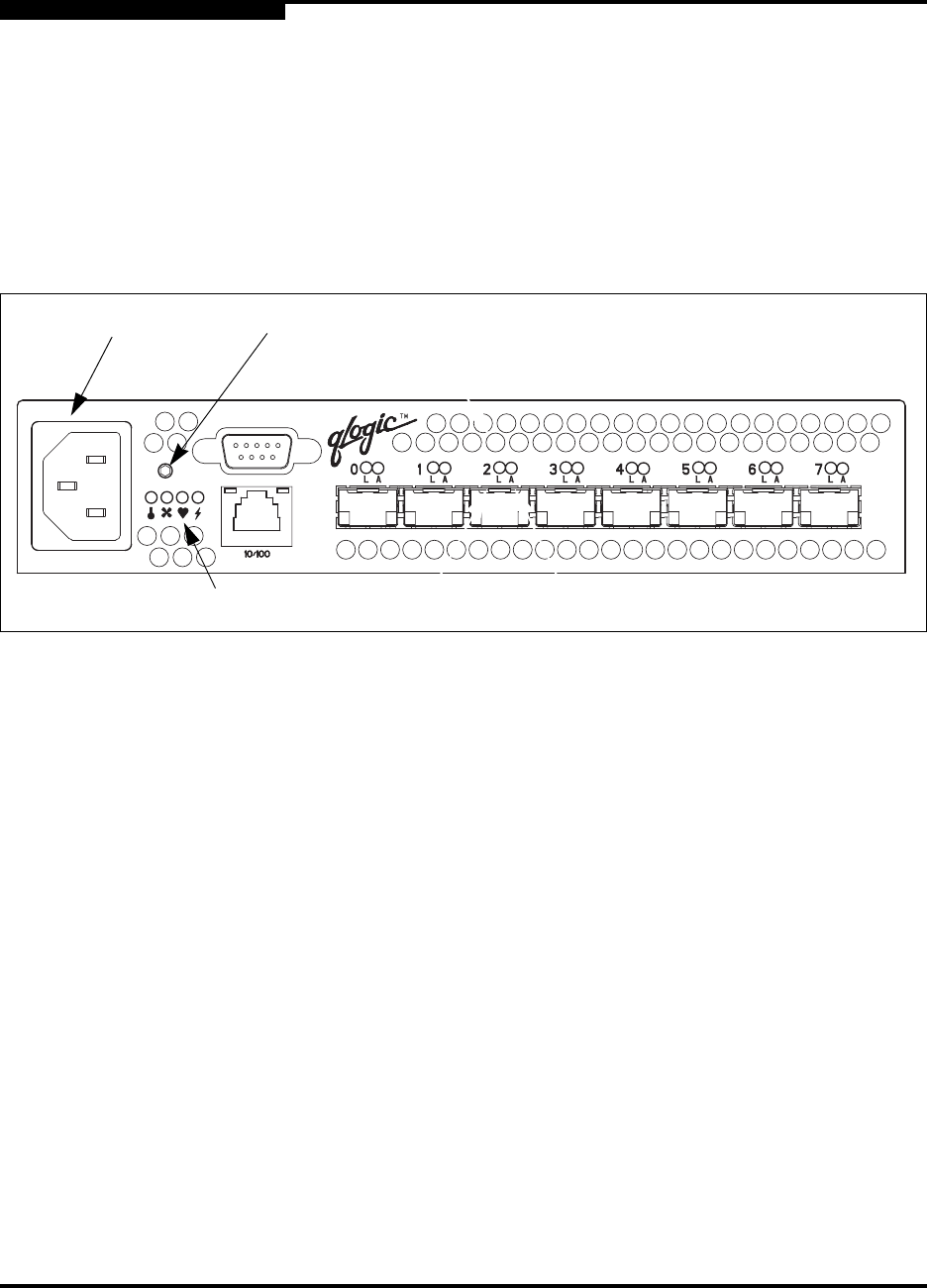
The Maintenance button shown in Figure 2-2 is the only chassis control and is
used to reset a switch or to recover a disabled switch. The chassis LEDs provide
information about the switch’s operational status. These LEDS include the Over
Temperature LED, Fan Fail LED, Heartbeat LED, and the Input Power LED. To
apply power to the switch, plug the power cord into the switch AC power
receptacle and into a 110 or 230 VAC power source.
Figure 2-2. Chassis Controls and LEDS
2.1.1
Maintenance Button
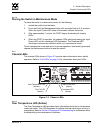
The Maintenance button is a dual-function momentary switch on the front panel.
Its purpose is to reset the switch or to place the switch in maintenance mode.
Maintenance mode sets the IP address to 10.0.0.1 and provides access to the
switch for maintenance purposes when flash memory or the resident configuration
file is corrupted. Refer to ”Recovering a Switch” on page 5-12 for more information
about using maintenance mode.
2.1.1.1
Resetting a Switch
To reset the switch, use a pointed tool to momentarily press and release (less than
2 seconds) the Maintenance button. The switch will respond as follows:
1. All of the chassis LEDs will illuminate and then extinguish leaving only the
Input Power LED illuminated.
2. After approximately 1 minute, the Power-On Self Test (POST) begins
illuminating all chassis LEDs.
3. When the POST is complete, the chassis LEDs extinguish leaving the Input
Power LED illuminated and the Heartbeat LED flashing once per second.
AC Power
Receptacle
Chassis LEDs
Maintenance
Button