


4 – Installation
Installing a Switch
4-4 59042-06 A
0
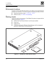
4.2.2
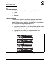
Install SFP Transceivers
The switch has been validated with transceivers that support a variety of
interconnection media. To install, insert the transceiver into the port and gently
press until it snaps in place. To remove a transceiver, gently press the transceiver
into the port to release the tension, then pull on the release tab or lever and
remove the transceiver. Different transceiver manufacturers have different release
mechanisms. Consult the documentation for your transceiver.
CAUTION!
If the switch is mounted in a closed or multi-unit rack
assembly, make sure that the operating temperature inside the
rack enclosure does not exceed the maximum rated ambient
temperature. Refer to ”Environmental” on page A-4.
The switch must rest on rails or a shelf in the rack or cabinet.
Allow 16 cm (6.5 in) minimum clearance at the front and rear of
the rack for service access and ventilation.
Do not restrict chassis air flow. Allow 16 cm (6.5 in) minimum
clearance at the front and rear of the rack for service access and
ventilation.
Multiple rack-mounted units connected to the AC supply
circuit may overload that circuit or overload the AC supply
wiring. Consider the power source capacity and the total power
usage of all switches on the circuit. Refer to ”Electrical” on
page A-3.
Reliable grounding in the rack must be maintained from the
switch chassis to the AC power source.
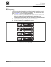
Note: The SFP transceiver will fit only one way. If the SFP does not install
under gentle pressure, flip it over and try again.