


2 – General Description
Fibre Channel Ports
2-4 59042-06 A
0
2.1.2.2
Fan Fail LED (Amber)
The Fan Fail LED indicates operational status of the fan. This LED illuminates if
the speed of the fan falls below the normal range. If the Fan Fail LED illuminates,
isolate the switch from the fabric, unplug the switch from the AC power source,
and contact your authorized maintenance provider.
2.1.2.3
Heartbeat LED (Amber)
The Heartbeat LED indicates the status of the internal switch processor and the
results of the Power On Self Test (POST). Following a normal power-up, the
Heartbeat LED blinks about once per second to indicate that the switch passed
the POST and that the internal switch processor is running. In maintenance mode,
the Heartbeat LED illuminates continuously. Refer to ”Heartbeat LED Blink
Patterns” on page 5-2 for more information about Heartbeat LED blink patterns.
2.1.2.4
Input Power LED (Green)
The Input Power LED indicates the voltage status at the switch logic circuitry.
During normal operation, this LED illuminates to indicate that the switch logic
circuitry is receiving the proper DC voltages.
2.2
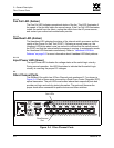
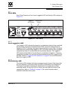
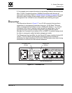
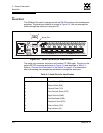
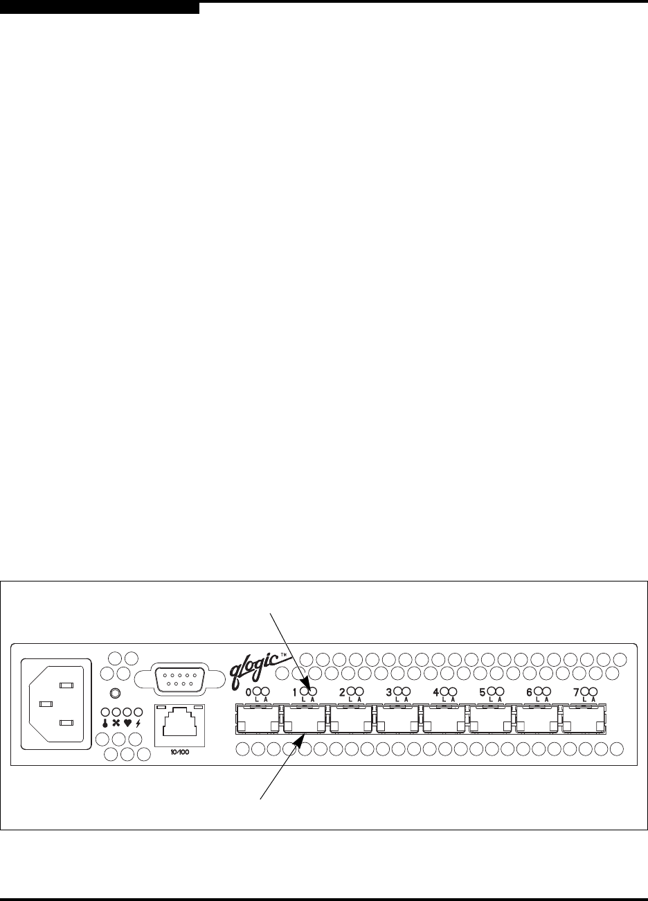
Fibre Channel Ports
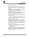
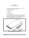
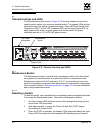
The SANbox2-8c switch has 8 Fibre Channel ports numbered 0–7 as shown in
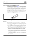
Figure 2-4. Each of these ports is served by a Small Form-Factor Pluggable (SFP)
optical transceiver. The port LEDs are located above their respective ports and
provide port login and activity status information. The ports self discover the
proper mode when connected to public devices and other switches.
Figure 2-4. Fibre Channel Ports
Fibre Channel
Port
Port LEDs