HighWire HW400c/2 User Reference Guide Rev 1.0
2.10.5 Switches
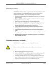
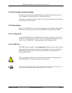
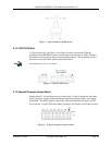
The HW400c/2 contains single switch that is necessary for normal operation. The
switch is an integral part of the lower ejector handle inside the front panel, and is
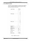
used along with the blue LED (see Figure 3) and the Linear Systems LTC1644, for
hot swap. The switch is connected to the PC board at J10 near the lower ejector
handle.
For debugging purposes an optional reset/NMI toggle switch and cable is available
(see Section 3.1.3). Please contact SBE Technical Support for details.
2.10.6 Product Configurations
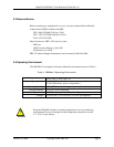
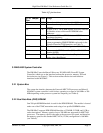
The HW400c/2 can be manufactured with several configuration options. Specific
options include processor type and speed, memory amount, and CompactPCI
connector configuration. See Table 6, Table 16, and Section 3.2.3 for related
information.
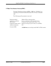
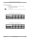
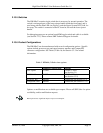
Table 5. HW400c/2 Order time options
Standard Configuration Options
CPU Speed 1.0 GHz 1.4 Ghz, 1.7Ghz
(see Section 3.1)
DDR RAM 256MB 512MB, 1GB
(see Section 3.2.2)
H.110 CT bus Installed Uninstalled (see Section 3.3.3)
CompactPCI bus Installed Uninstalled (See Section 3.2.3)
Options or modifications are available upon request. Please call SBE Sales for option
availability, and/or modification requests.
Build options have significant impact on power consumption.
October 10, 2006 Copyright 2006, SBE, Inc. Page 12


