HighWire HW400c/2 User Reference Guide Rev 1.0
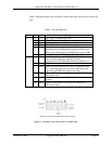
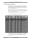
Table functions
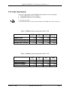
.1 Jumper
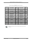
8. J7 pin
3.1.5
Pins
Label Usage
1-2 PWR Forces board “late power” to switch “ON” at power-up
3-4 IGNP Forces board to operate as if no Host PCI bus is
present
5-6 FAC a) Sets “FACT” bit in BSR register for use by so
b) Enables writes to Microwire EEPROM lower
ftware
addresses
7-8 LPCI Limits Local PCI bus (PTMC sites) to 100MHz
maximum frequency
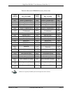
9-10 IRST Holds IPMI Controller (U92) in reset state. (Required
hen programming IPMI EEPROMs on-board via the
w
System Controller TWSI interface, see Table 7).
11-12 IWE Enables writes to the I
2
C Configuration ROM (U30)
13-14 ZJT Connects only IPMI Controller (U92) to JTAG/COP
header (J6/JX6)
15-16 TRST Forces JTAG Reset signal inactive (Required when
using Altera ByteBlaster)
3.2 MV64462 Sy
interface between the processor, memory, PCI and
evice busses (see Figure 1). This section outlines the devices and functions
rfaced to the MV64462.
3.2.1 System Bu
nd Marvell
V64462 system controller is a 64-bit bus, operating at a speed of 166 MHz or 200
cessor system bus frequency (see Table 6).
3.2.2 Dual Data
e memory speed is the same as the processor bus speed, and therefore
e memory speed for the standard MPC7447A (1 GHz) configuration is 166 MHz
(see Table 6).
stem Controller
The HW400c/2 uses the Marvell Discovery III (MV64462) PowerPC System
ontroller, which acts as the C
d
inte
s
he system bus interface between the Freescale MPC744X processor aT
M
MHz depending on the pro
Rate (DDR) SDRAM
One 200-pin SODIMM module is used for the DDR SDRAM. The module is located
under one of the PTMC mezzanine cards using a low-profile SODIMM socket.
The HW400c/2 supports DDR SDRAM densities of 256 MB, 512 MB, and 1 GB as
order time options. Memory speeds of up to 200 MHz are supported for MPC7448
rocessors. Thp
th
October 10, 2006 Copyright 2006, SBE, Inc. Page 17


