HighWire HW400c/2 User Reference Guide Rev 1.0
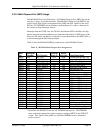
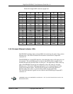
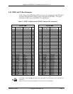
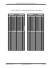
Table 1 t PC or J3 t
A B C D E
5. Compac I connect pin ou
1
+5.0v +5.0v
N/C N/C N/C
2
+5.0v +12v
N/C N/C N/C
3
N/C N/C N/C N/C N/C
4
LED Clock N/C N/C N/C N/C
5
N/C N/C N/C N/C N/C
6
LED Data N/C N/C N/C GND
7
N/C N/C N/C N/C N/C
8
+3.3v
N/C
GND GND
N/C
9
+3.3v
N/C N/C N/C GND
10
+3.3v
N/C N/C N/C N/C
11
N/C
GND GND
N/C N/C
12
N/C N/C N/C N/C N/C
13
N/C N/C N/C N/C N/C
14
GND GND GND GND GND
15
LPb DB+ LPb DB- GND LPb DD+ LPb DD-
16
LPb DA+ LPb DA- GND LPb DC+ LPb DC-
17
LPa DB+ LPa DB- GND LPa DD+ LPa DD-
18
LPa DA+ LPa DA- GND LPa DC+ LPa DC-
19
GND GND GND GND GND
3.4.6 On-board Ethernet Indicator LEDs
s for monitoring the status of the various
and are located near CompactPCI
m which the status of all eight ports can
e the CPLD, which contains a state
ac
LED Interface section in the
BCM5388 datasheet).
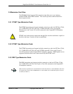
The HW400c/2 includes eight on-board LED
Ethernet ports. The LEDs are labeled L0-L8
connector J5.
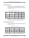
The BCM5388 has a serial LED interface, fro
be xtracted. The serial LED signal is routed to
hine that decodes the LED states for each port. The eight status LEDs on the top m
edge of the HW400c/2 board can be configured to show the status for all eight
Ethernet ports. Each status LED gives the status for its corresponding port in the
Link/Activity/Speed format. The CPLD LED registers control the selection of
Ethernet status, boot status, or general debug modes for the eight LEDs.
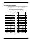
The serial LED interface signals are also routed to the RTM through CompactPCI
connector J3.
LEDMODE settings on the BCM5388 are hardwired to “101” (see Serial
October 10, 2006 Copyright 2006, SBE, Inc. Page 30


