HighWire HW400c/2 User Reference Guide Rev 1.0
3.6.6 Board Reset via IPMI
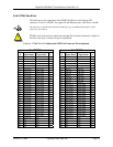
ble 22) is connected to the CPLD and OR’ed with the /P_RST
set signal from the Host CompactPCI bus. A standard IPMI command is issued to
initiate the board reset. IPMI commands are issued through an IPMI Shelf Manager
3.6.7 IPMI System Power Supply
IPMI
Zircon PM, together with all its supporting devices, draws about
0mA maximum continuous current. However, due to power-up inrush or a short
cuit, the current could exceed 100mA. Therefore, a current-limiting switch is
3.6.8 IPMI Firmw
here are two Atmel AT24C512 (64 KB) EEPROMs connected to I
2
C Port 2 on the
Zircon PM. The E he runtime firmware. The
EEPROM at U87 i of information related to Field
Replaceable Units (FRU), such as serial number. These assignments are shown in
Table 25.
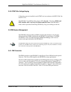
The EEPROMs can be pre-programmed (default), or th grammed on-
MV Serial Interface (TWSI), See Table 7.
The IPMI EEPROMs pre-programmed at the factory should always be used.
Programming on board is usually unnecessary, and is recommended only for expert
users, as misconfiguration could result in unpredictable behavior.
When programming the EEPROMs on-board, the Zircon PM must be held in the reset state by installing
the IRST jumper on the J7 header (see Table 8). Table 25 shows the I
2
C addresses of each EEPROM.
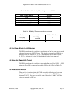
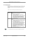
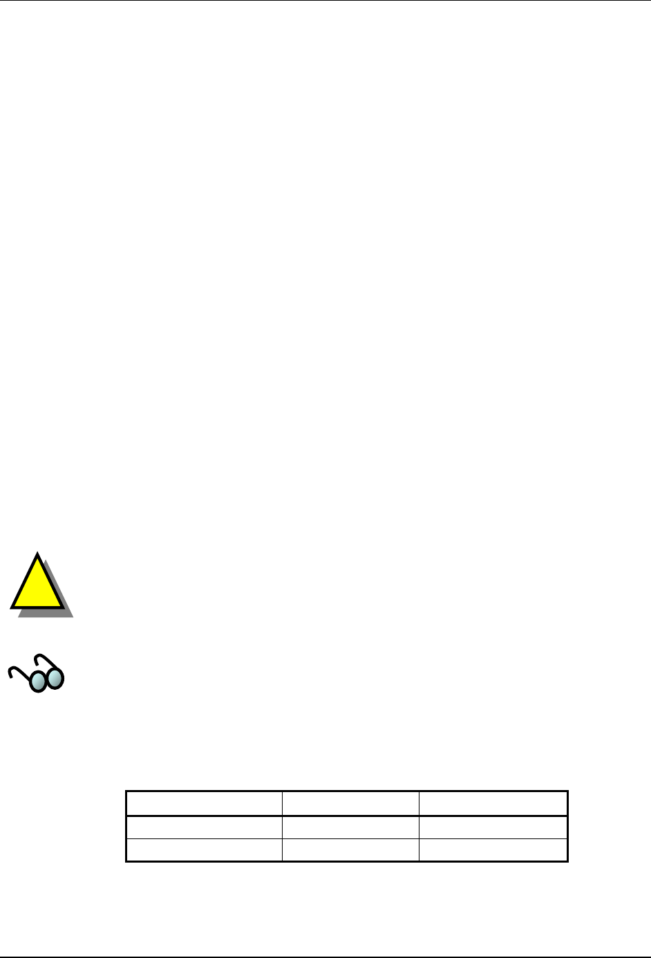
Table 25. Firmware EEPROM Addresses
EEPROM Function EEPROM Type I
2
C Port 2 Address
The IPMI controller has the capability to issue a board reset. A GPIO port on the
Zircon PM (see Ta
re
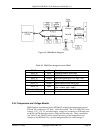
The Vsm supply pin on the CompactPCI J1 connector delivers 5V to the
circuit. The PICMG 2.9 specification sets the maximum current drawn from the Vsm
pin at 100mA. The
6
cir
connected at the Vsm pin.
are EEPROMs
T
EPROM at U90 is for storage of t
s for boot code, as well as storage
ey can be pro
board via the
64462 Two-Wire
!
Boot/FRU (U87) AT24C512 0
Runtime (U90) AT24C512 1
October 10, 2006 Copyright 2006, SBE, Inc. Page 42


