


ELECTRICAL SPECIFICATIONS
4
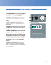
Connect the laminator in accordance with the details
given on the identification plate attached to the rear
of the laminator. Refer also to the Technical
Specifications page for more information.
Single Phase Version:
(Part No. 60424)
For areas where the voltage requirements are
200-240V, the following is applicable:
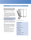
CONNECTING YOUR LAMINATOR
All domestic laminators will be shipped without a power
cord. It is required that only a qualified electrician provides
power to the laminator or the warranty will be void. We
recommend a Ground Fault Interrupter (GFI) circuit
breaker with a 60-amp load rating, not exceeding a
100-amp load rating. Use 3/6 AWG power cord, Type
SOW-A/SO rated to 90°C/194° F and 600 Volts. See
Figure 1 Wiring Diagram for detailed information. For
European laminators use a Residual Current Device
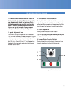
(RCD/RCCD). Once power is connected to your lamina-
tor, press the Stand-By Switch UP on the front control
panel to turn the laminator ON. If you have no display,
refer to the “Troubleshooting” page for problem-solving
information.
WARNING! Any unauthorized changes or modifica-
tions to this unit without our prior written approval
will void the user’s warranty and will transfer health
and safety obligations to the user.
IMPORTANT! SEAL Graphics recommends that a
licensed electrician, in accordance with electrical codes
in your area, install your mains power. Specifications
subject to change without notice.
IMPORTANT! The mains outlet should be fused no
higher than 60 Amp, Three-phase -or- 100 Amp,
Single-phase.
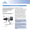
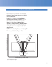
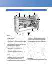
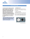
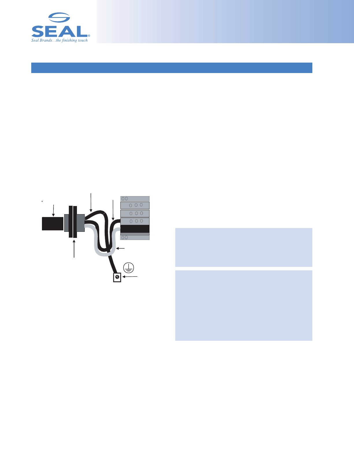
Figure 1. Wiring Diagram
Power cord:
3/6 AWG,
Type SOW-A/SO
Black Wire
White Wire
Earth Ground
Power Cord Strain Relief:
Turn clockwise to tighten.
**IMPORTANT: The ground (green wire) should be
two inches longer than the black and white wires
to fit into the grounding lug.
Grounding Lug
90 C/194° F, 600 Volts