Chapter 1. Overview
May 2002 T-38324-A Page 1-7
Using the Siemens 3964R Barcode Protocol
The RS-422 port on the controller supports the Siemens 3964R barcode protocol. This protocol
provides an error checked point-to-point method of sending barcode data to the controller. If the
controller receives a corrupt or incomplete barcode, the scanner sends the barcode information again.
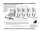
For example, you might choose to attach a barcode scanner and controllers to the same RS-422
network. A barcode is read by the scanner, which then sends the barcode to every controller attached
to the network. This means you do not have to scan the barcode at each individual controller.
NOTE: If, for any reason, the scanner does not send a barcode using
the RS-422 port, then the Printer/Barcode port on each
controller provides you with a backup. You can always scan the
barcode at an individual controller using a scanner attached to
the Printer/Barcode serial port until the scanner attached to the
RS-422 port starts sending barcode data again.
For further details about the Siemens 3964R Barcode Protocol, refer to the Protocol Definition of the
3964/3964R Procedures available from Siemens (Siemens Part Number C79000-B8576-C191-01).
Deciding How to Set Up the Controller
It is more than likely that you will not need to use all methods of connecting the controller to a
network and/or external devices. If you decide to use the 485 network link then you will not need the
Ethernet link, nor vice versa, as they perform the same function. You may or may not want the
controller to communicate with a PLC and/or an external barcode scanner, in which case, you do not
need an Interbus-S I/O module or a link via the RS-422 port.
The following chapter describes the basic components of the controller so you can familiarize yourself
with them before you install it. Chapter 4. Installing the CS4000 Mini Controller with Ethernet
describes how to mount the controller and how to make sure you fulfill its power requirements.
Chapter 5. Setting Up the Ethernet, Chapter 6. Setting Up the 485 Network and Chapter 7. Setting Up
the RS-232 Link describe how to install the various components that have been discussed in this
chapter.


