


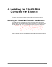
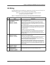

Chapter 4. Installing the CS4000 Mini Controller with Ethernet
May 2002 T-38324-A Page 4-9
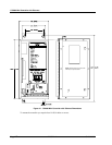
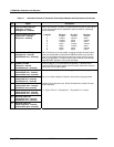
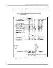
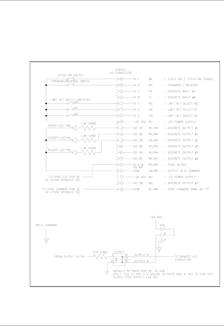
Figure 4-4 is an example of the remote I/O wiring scheme using the defaults (voltage source) for the
jumpers. It shows one of the many ways the remote I/O feature of the controller can be used. To
ensure that you operate the fastening system properly, refer to Table 4-2 for output requirements. See
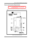
Figure 3-8 on page 3-11 for the locations of JP1 to JP9 on the backplane.
NOTE: JP9 ties discrete output 8 to discrete input 6 for spindle
synchronization.
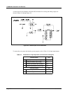
Figure 4-4. Example of CS4000 Controller Remote I/O Wiring −
−−
− Sourcing Outputs