Chapter 3. Identifying the Components
May 2002 T-38324-A Page 3-15
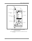
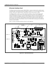
The nine-position RS-232 serial port, J7, is used for setup and diagnostics of the Ethernet interface
card. You can change the Ethernet application program or the TCP/IP information by using TINI
Ethernet Interface Flash Utility on a laptop connected to the Ethernet interface card, via J7. Refer to
Chapter 4. Installing the CS4000 Mini Controller with Ethernet for further details.
You can also obtain diagnostics information on the state of the Ethernet network through the Ethernet
interface card using Hyperterminal. Refer to Chapter 8. Maintenance/Troubleshooting for further
details.
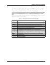
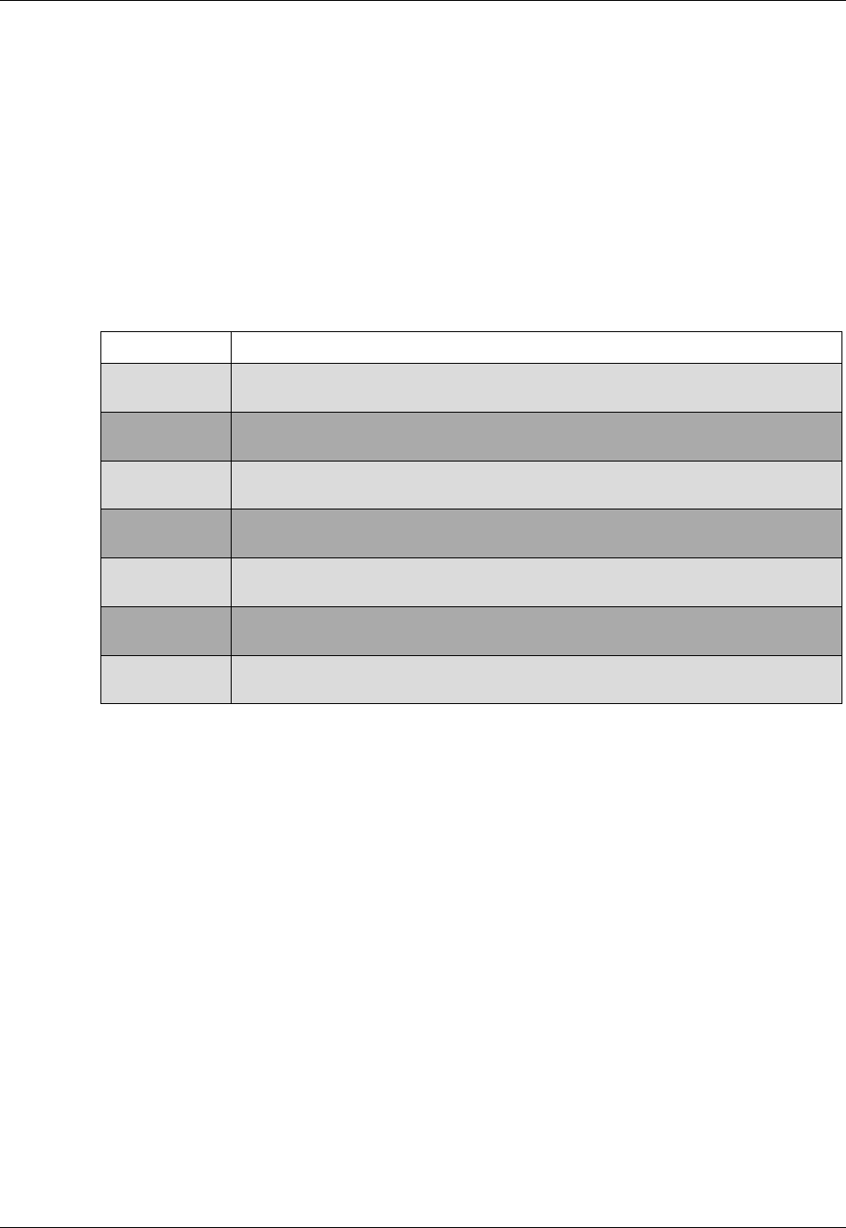
Table 3-1 describes the LEDs on the Ethernet interface card. Each LED lights up steadily or flashes to
indicate the current state of I/O connections.
Table 3-1. Description of Ethernet Interface Card LEDs
LED Name Description
LED1 (5V)
Steady red light indicates the power supply is connected to the Ethernet interface
card.
LED2 (A)
Flashing red light indicates communication between the controller and the host
device of the Ethernet LAN using the Application Program Interface (API).
LED3 (B)
Flashing red light indicates Visual Supervisor communication between the
controller and the host device of the Ethernet LAN.
LED4 (C)
Flashing red light indicates local Visual Supervisor communication between the
controller and any PC that is attached to it, via an RS-232 connection.
LED5 (D)
Flashing red light indicates communication (Siemens 3964R) between the
controller and the scanner using the RS-422 communications port.
LED6 (E)
Flashing yellow light indicates communication between the Ethernet interface
card and the TCM.
LED7 (F)
Steady green light indicates successful power up initialization of the Ethernet
interface card software.


