


Chapter 3. Identifying the Components
May 2002 T-38324-A Page 3-3
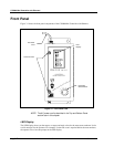
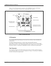
Parameter Set Switch
Turn the dial to select the parameter set you wish to use for the next rundown. Select parameter sets
using the parameter set switch or Visual Supervisor.
Access Screws
The access screws keep the front panel of the controller fastened. To un-fasten them you need a No.2
cross-tip (Phillips) head screwdriver.
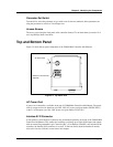
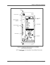
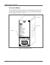
Top and Bottom Panel
Figure 3-2 shows the top panel components of the CS4000 Mini Controller with Ethernet.
Figure 3-2. Top Panel View
AC Power Cord
A power cord connection is available on the top of CS4000 Mini Controller with Ethernet. The power
cords it accepts are the 6-ft American style 20A, 240V AC power cord (part number 299250-32835)
or the 2.5-m European style 10A, 240V power cord (part number 22-30-1021).
Interbus-S I/O Connector
A nine-position, serial Interbus-S connector may be mounted optionally on the top of the CS4000 Mini
Controller with Ethernet. This enables the controller to exchange up to eight digital inputs and outputs
with an external Programmable Logic Controller (PLC). If an Interbus-S module is not included in the
controller, the Interbus-S I/O connector is covered. To find out details about the Interbus-S module,
refer to the Interbus-S Module section later in this chapter.
AC Power Cord
Interbus-S I/O Connector
(Optional)