


CS4000 Mini Controller with Ethernet
Page
3-4
T-38324-A 39-30-38324
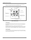
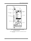
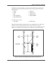
Figure 3-3 shows the bottom panel components of the CS4000 Mini Controller with Ethernet.
Descriptions are provided in clockwise order, starting with the I/O connector.
Figure 3-3. Bottom Panel View
I/O Connector
The 19-position remote I/O connector provides the interface between external control/monitoring
devices and the internal control electronics. tech-motive tool accessories, such as socketrays, are
connected here.
The mating connector for this port is a 14-shell, 19-pin, strain relief (SR) connector
(part number 23-10-5200). The mating connector enables connection of your own remote control
and/or monitoring devices, such as external annunciator lamps or remote cycle-on contacts. Refer to
I/O Wiring in Chapter 4. Installing the CS4000 Mini Controller with Ethernet for pinout details.
Tool Connector
The 37-position connector is the interface between the 46, 66 and 116 Series nutrunner cable and
control electronics. Refer to Connector Pinout Definitions in Chapter 4. Installing the CS4000 Mini
Controller with Ethernet for pinout details.
ETHERNET
PRINTER/BARCODE
TCM SDLC NETWORK
IN
FUSE 2
OUT
RS232
A
I/O
FUSE 1
RS422
Fuses
Ground Fault Circuit
Interrupter (GFCI)
I/O Connector
Tool Connector
RJ-45 Ethernet Connector
Printer/Barcode Connector
RS-232 Connector
RS-422 Connector
SDLC I/O Network Connector