


Chapter 4. Installing the CS4000 Mini Controller with Ethernet
May 2002 T-38324-A Page 4-7
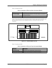
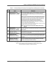
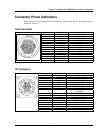
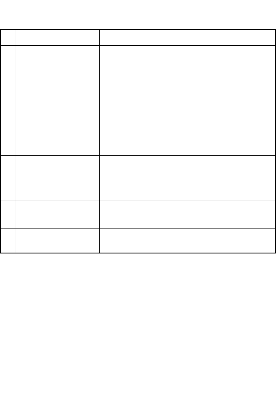
Table 3-1. 19-Position Remote I/O Connector Pinout Signal Names and Descriptions (Continued)
Pin Signal Description
R Synchronization in/out
(White/Orange wire - internal)
(Orange/Red wire - external)
This bi-directional signal is used for synchronizing two or more spindles
in a multi-spindle fastening application. It is connected to both the
synchronization output (Discrete output #8) and the synchronization input
(Discrete input #6).
If Sync is set to On, the synchronization output becomes active when a
fastening cycle is started. When the nutrunner output torque reaches the
Control Reference level, the synchronization output is de-activated. At
the same time, the state of the synchronization input is sampled. If it is
still active because some other spindle has not reached the
synchronization level yet, it stops the nutrunner and waits for the
synchronization input to become inactive. Afterwards, it re-starts the
nutrunner and finishes the fastening cycle.
This pin should be connected to the synchronization in/out pin of all other
spindles for which synchronization is desired.
NOTE: This feature only functions when JP8 and JP9 are set to
defaults.
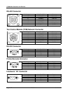
S Output common
(White/Brown wire - internal)
(Blue/white wire - external)
This pin is connected to the negative terminal (-) of the internal 24VDC
I/O power supply and is normally used as the common connection for the
output signals.
T CS4000 +24 VDC
(Blue wire - internal)
(Black/Red wire - external)
This pin (and pin H) is connected to the positive (+) terminal of the
internal 24VDC I/O power supply and is normally used as the common
connection for the input signals.
U Discrete output #7*
(Brown wire - internal)
(White/Red wire - external)
Pins U and J, K, L, M, N, and P are the programmable discrete outputs.
Any one of these outputs will become active when its programmed output
function becomes true. The functions of these outputs are set with VS
set output.
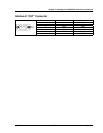
V Synchronization common
(Violet wire - internal)
(Blue/Red wire - external)
This is the common connection for the synchronization input/output. It
should be connected to the synchronization common pin of all other
spindles for which synchronization is desired.
*Early units have these outputs fixed in the software. Units with KDM software 2.5 or later have configurable outputs.
NOTE: Active means an input is connected to +24VDC. Inactive means
an input is either not wired or is wired to common.