


Chapter 4. Installing the CS4000 Mini Controller with Ethernet
May 2002 T-38324-A Page 4-5
I/O Wiring
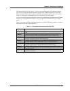
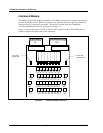
The CS4000 Mini Controller with Ethernet is equipped with a 19-pin I/O connector for field I/O. The
settings described in Table 4-1 are Visual Supervisor (VS) default settings.
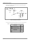
NOTE: The 14-shell, 19-pin strain relief mating connector for the I/O
connector is part number 23-10-5200.
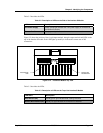
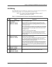
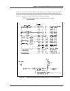
Table 4-1. 19-Position Remote I/O Connector Pinout Signal Names and Descriptions
Pin Signal Description
A Cycle On/Cycle On Enable
Clear Outputs
(Black wire - internal)
(Black wire - external)
This is a dual-purpose input.
When Set Defaults is clicked, VS sets this input to Start, this input
functions as a cycle on input. This means a fastening cycle can be
started by either pressing the throttle/trigger switch on the nutrunner OR
by activating this input.
When remote mode for the spindle is set to enable, this input functions
as a cycle on enable input. This means a fastening cycle can be started
only by pressing both the throttle/trigger switch on the nutrunner and
activating this input.
In addition, it is also set to Clear Outputs.
This is a level-sensitive input. For the fastening cycle to proceed, this
input must remain active. If this input becomes inactive at any time
during the fastening cycle, the cycle will be aborted and the nutrunner
will stop running.
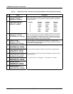
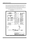
B Forward/Reverse input
(White wire internal)
(White wire - external)
When Set Defaults is clicked, VS sets this input to the direction the
nutrunner turns in a fastening cycle:
If this input is active when a fastening cycle is started, the nutrunner will
run in the forward (fastening or tightening) direction. If this input is
inactive when a fastening cycle is started, the nutrunner will run in the
reverse (un-fastening or loosening) direction.
After a fastening cycle has started, changing the state of this input has
no effect on the fastening direction until the cycle on command (from
either the nutrunner or the cycle on input or both) is de-activated. This
means the input must be in the desired state BEFORE activation of the
cycle start input.
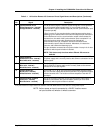
C Discrete Input #7
(Gray wire - internal)
(Red wire - external)
Defaults to “Manual Calibration.”
D Discrete Input #8
(Yellow wire - internal)
(Green wire - external)
Multi-purpose switch input “OR” function with switch on tool.