


uPSD3212A, uPSD3212C, uPSD3212CV
118/163
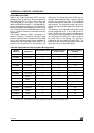
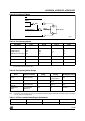
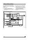
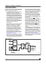
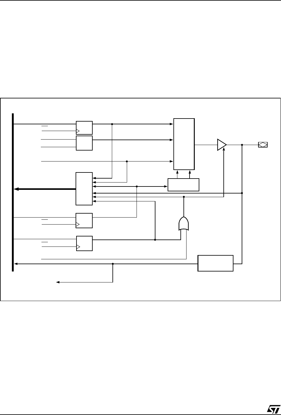
Ports A and B – Functionality and Structure
Ports A and B have similar functionality and struc-
ture, as shown in Figure 61. The two ports can be
configured to perform one or more of the following
functions:
■ MCU I/O Mode
■ CPLD Output – Macrocells McellAB7-
McellAB0 can be connected to Port A or Port
B. McellBC7-McellBC0 can be connected to
Port B or Port C.
■ CPLD Input – Via the Input Macrocells (IMC).
■ Latched Address output – Provide latched
address output as per Table 91., page 115.
■ Open Drain/Slew Rate – pins PA3-PA0 and
PB3-PB0 can be configured to fast slew rate,
pins PA7-PA4 and PB7-PB4 can be
configured to Open Drain Mode.
■ Peripheral Mode – Port A only (80-pin
package)
Figure 61. Port A and Port B Structure
MCU DATA BUS
DATA OUT
REG.
DQ
D
G
Q
DQ
DQ
WR
WR
WR
ADDRESS
MACROCELL OUTPUTS
ENABLE PRODUCT TERM
(
.OE
)
ALE
READ MUX
P
D
B
CPLD-INPUT
CONTROL REG.
DIR REG.
INPUT
MACROCELL
ENABLE OUT
DATA IN
OUTPUT
SELECT
OUTPUT
MUX
PORT
A OR B PIN
DATA OUT
ADDRESS
A
[
7:0
]
AI06605