


uPSD3212A, uPSD3212C, uPSD3212CV
86/163
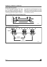
External USB Pull-Up Resistor
The USB system specifies a pull-up resistor on the
D- pin for low-speed peripherals. The USB
Spec 1.1 describes a 1.5kΩ pull-up resistor to a
3.3V supply. An approved alternative method is a
7.5kΩ pull-up to the USB V
CC
supply. This alterna-
tive is defined for low-speed devices with an inte-
grated cable. The chip is specified for the 7.5kΩ
pull-up. This eliminates the need for an external
3.3V regulator, or for a pin dedicated to providing
a 3.3V output from the chip.
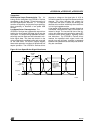
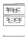
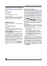
Figure 42. USB Data Signal Timing and Voltage Levels
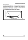
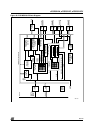
Figure 43. Receiver Jitter Tolerance
AI06631
VCR
D-
D+
t
R
t
F
10%
90%
90%
10%
V
OH
V
OL
AI06632
T
JR
T
JR1
T
JR2
Consecutive
Transitions
N*T
PERIOD
+T
JR1
T
PERIOD
Paired
Transitions
N*T
PERIOD
+T
JR2
Differential
Data Lines