


uPSD3212A, uPSD3212C, uPSD3212CV
50/163
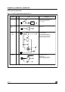
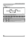
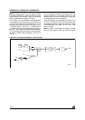
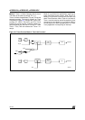
Mode 0. Putting either Timer into Mode 0 makes
it look like an 8048 Timer, which is an 8-bit Counter
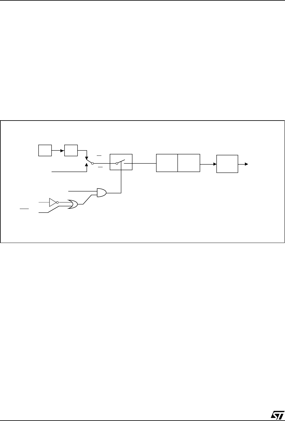
with a divide-by-32 prescaler. Figure 22 shows the
Mode 0 operation as it applies to Timer 1.
In this mode, the Timer register is configured as a
13-bit register. As the count rolls over from all '1s'
to all '0s,' it sets the Timer Interrupt Flag TF1. The
counted input is enabled to the Timer when TR1 =
1 and either GATE = 0 or /INT1 = 1. (Setting GATE
= 1 allows the Timer to be controlled by external in-
put /INT1, to facilitate pulse width measurements).
TR1 is a control bit in the Special Function Regis-
ter TCON (TCON Control Register). GATE is in
TMOD.
The 13-bit register consists of all 8 bits of TH1 and
the lower 5 bits of TL1. The upper 3 bits of TL1 are
indeterminate and should be ignored. Setting the
run flag does not clear the registers.
Mode 0 operation is the same for the Timer 0 as
for Timer 1. Substitute TR0, TF0, and /INT0 for the
corresponding Timer 1 signals in Figure 22. There
are two different GATE Bits, one for Timer 1 and
one for Timer 0.
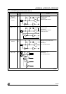
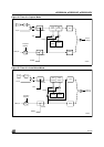
Mode 1. Mode 1 is the same as Mode 0, except
that the Timer register is being run with all 16 bits.
Figure 22. Timer/Counter Mode 0: 13-bit Counter
AI06622
f
OSC
TF1 Interrupt
Gate
TR1
INT1 pin
T1 pin
Control
TL1
(5 bits)
TH1
(8 bits)
C/T = 0
C/T = 1
÷ 12