


27/163
uPSD3212A, uPSD3212C, uPSD3212CV
uPSD3200 HARDWARE DESCRIPTION
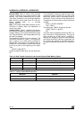
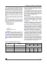
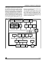
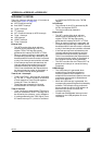
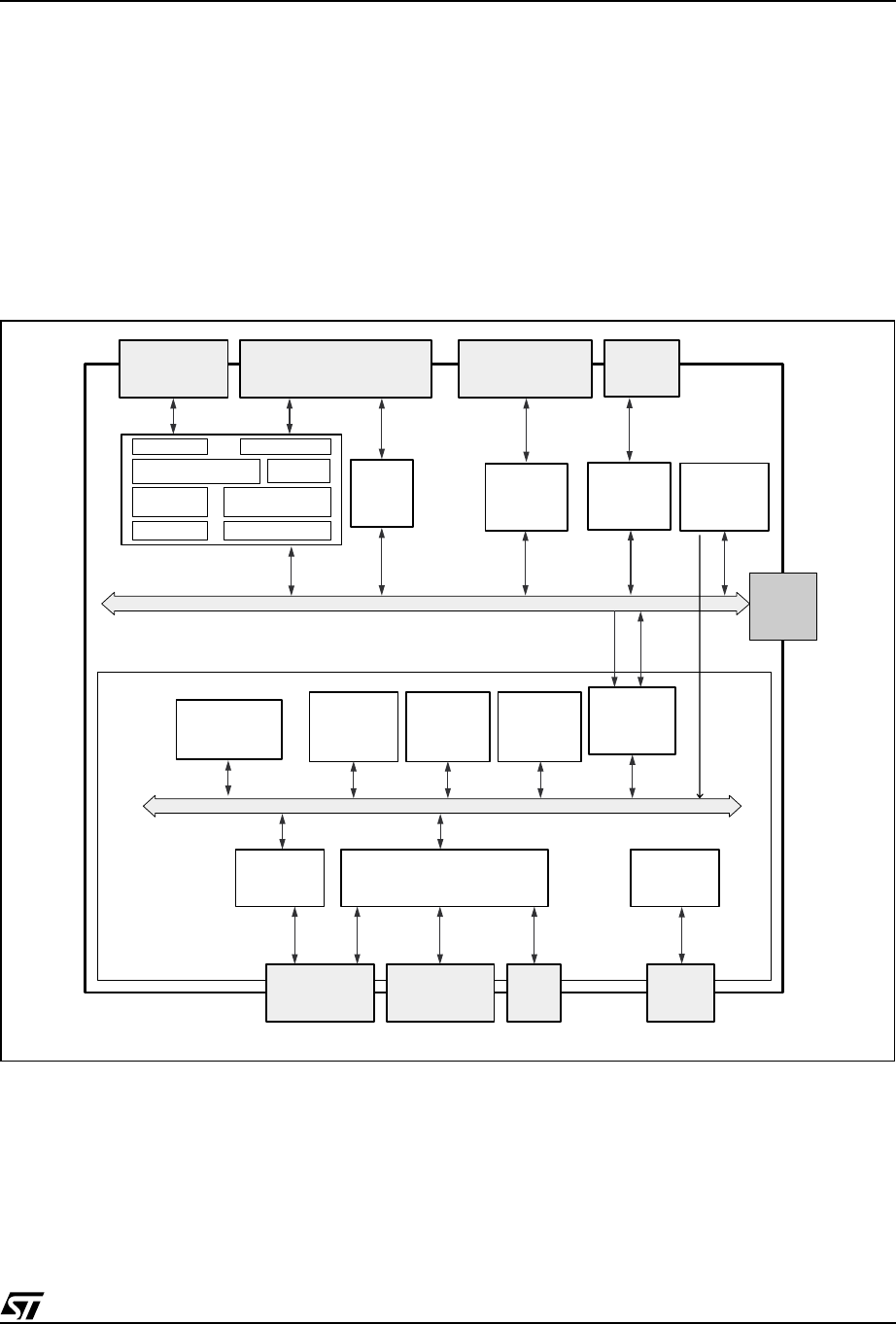
The uPSD321x Devices has a modular architec-
ture with two main functional modules: the MCU
Module and the PSD Module. The MCU Module
consists of a standard 8032 core, peripherals and
other system supporting functions. The PSD Mod-
ule provides configurable Program and Data mem-
ories to the 8032 CPU core. In addition, it has its
own set of I/O ports and a PLD with 16 macrocells
for general logic implementation. Ports A,B,C, and
D are general purpose programmable I/O ports
that have a port architecture which is different from
Ports 0-4 in the MCU Module.
The PSD Module communicates with the CPU
Core through the internal address, data bus (A0-
A15, D0-D7) and control signals (RD_, WR_,
PSEN_ , ALE, RESET_). The user defines the De-
coding PLD in the PSDsoft Development Tool and
can map the resources in the PSD Module to any
program or data address space.
Figure 15. uPSD321x Devices Functional Modules
AI07426b
4
Channel
ADC
512Kb
Main Flash
Decode PLD
16Kb
SRAM
CPLD - 16 MACROCELLSJTAG ISP
Port 1Port 3
2 UARTs
Interrupt
3 Timer /
Counters
256 Byte SRAM
8032 Core
Port 3, UART,
Intr, Timers,I
2
C
PSD Internal Bus
8032 Internal Bus
Port 1, Timers and
2nd UART and ADC
PWM
5
Channels
Port 4 PWM
Port A & B, PLD
I/O and GPIO
Port D
GPIO
Port C,
JTAG, PLD I/O
and GPIO
VCC, GND,
XTAL
128Kb
Secondary
Flash
Dedicated
Pins
I2C
Port 0, 2
Ext. Bus
Reset Logic
LVD & WDT
Bus
Interface
Reset
D0-D7
A0-A15
RD,PSEN
WR,ALE
Page Register
PSD MODULE
MCU MODULE
USB
&
Transceiver
Dedicated
USB Pins