


133/163
uPSD3212A, uPSD3212C, uPSD3212CV
DC AND AC PARAMETERS
This section summarizes the operating and mea-
surement conditions, and the DC and AC charac-
teristics of the device. The parameters in the DC
and AC Characteristic tables that follow are de-
rived from tests performed under the Measure-
ment Conditions summarized in the relevant
tables. Designers should check that the operating
conditions in their circuit match the measurement
conditions when relying on the quoted parame-
ters.
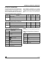
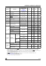
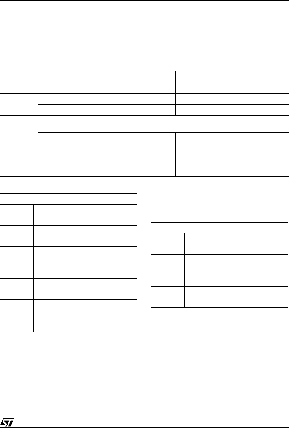
Table 109. Operating Conditions (5V Devices)
Table 110. Operating Conditions (3V Devices)
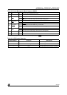
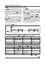
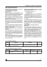
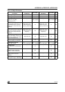
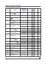
Table 111. AC Signal Letter Symbols for Timing
Note: Example: t
AVLX
= Time from Address Valid to ALE Invalid.
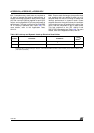
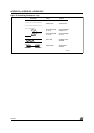
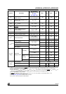
Table 112. AC Signal Behavior Symbols for
Timing
Note: Example: t
AVLX
= Time from Address Valid to ALE Invalid.
Symbol Parameter Min. Max. Unit
V
CC
Supply Voltage 4.5 5.5 V
T
A
Ambient Operating Temperature (Industrial) –40 85 °C
Ambient Operating Temperature (Commercial) 0 70 °C
Symbol Parameter Min. Max. Unit
V
CC
Supply Voltage 3.0 3.6 V
T
A
Ambient Operating Temperature (Industrial) –40 85 °C
Ambient Operating Temperature (Commercial) 0 70 °C
Signal Letters
A Address
C Clock
D Input Data
I Instruction
LALE
N RESET
Input or Output
P PSEN
signal
Q Output Data
R RD signal
W WR signal
B
V
STBY
Output
M Output Macrocell
Signal Behavior
tTime
L Logic Level Low or ALE
H Logic Level High
V Valid
X No Longer a Valid Logic Level
ZFloat
PW Pulse Width