


uPSD3212A, uPSD3212C, uPSD3212CV
70/163
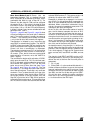
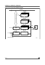
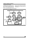
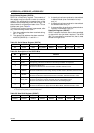
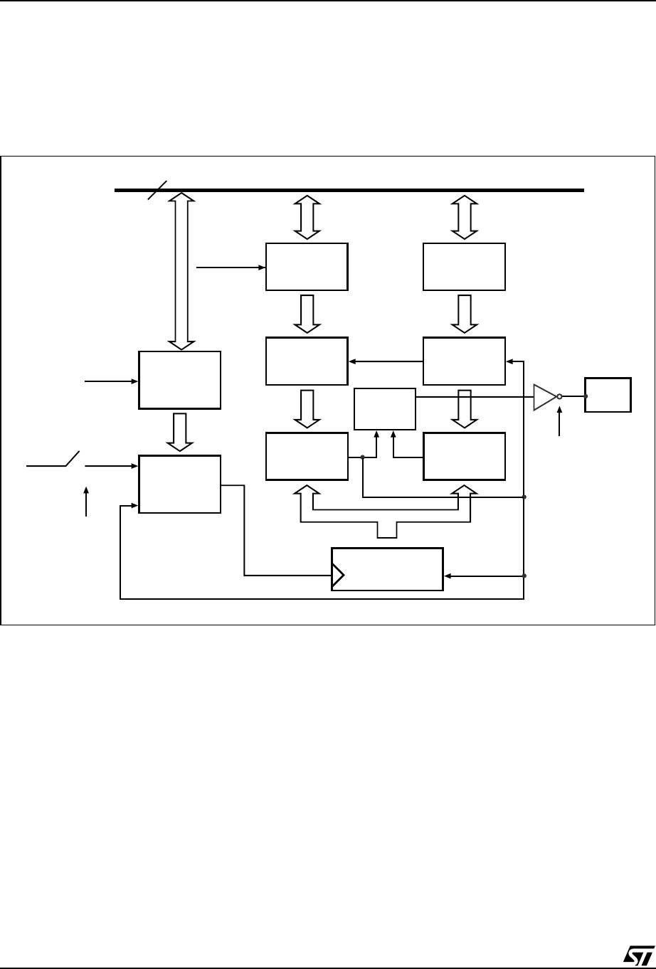
Programmable Period 8-bit PWM
The PWM 4 channel can be programmed to pro-
vide a PWM output with variable pulse width and
period. The PWM 4 has a 16-bit Prescaler, an 8-
bit Counter, a Pulse Width Register, and a Period
Register. The Pulse Width Register defines the
PWM pulse width time, while the Period Register
defines the period of the PWM. The input clock to
the Prescaler is f
OSC
/2. The PWM 4 channel is as-
signed to Port 4.7.
Figure 37. Programmable PWM 4 Channel Block Diagram
AI07091
Port 4.7
16-bit Prescaler
Register
(B4h, B3h)
16-bit Prescaler
Counter
8-bit Counter
8-bit PWM4P
Register
(Period)
8-bit PWM4
Comparator
Register
8-bit PWM4
Comparator
PWM4
Control
Match
CPU RD/WR
Load
Load
Clock
Reset
PWMCON
Bit 6 (PWMP)
DATA BUS
CPU RD/WR
f
OSC
/ 2
PWMCON
Bit 5 (PWME)
8
16
8
8
8
8
8-bit PWM4W
Register
(Width)
8-bit PWM4
Comparator
Register
8-bit PWM4
Comparator
8
88
8
8