


125/163
uPSD3212A, uPSD3212C, uPSD3212CV
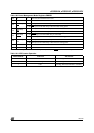
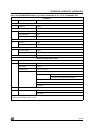
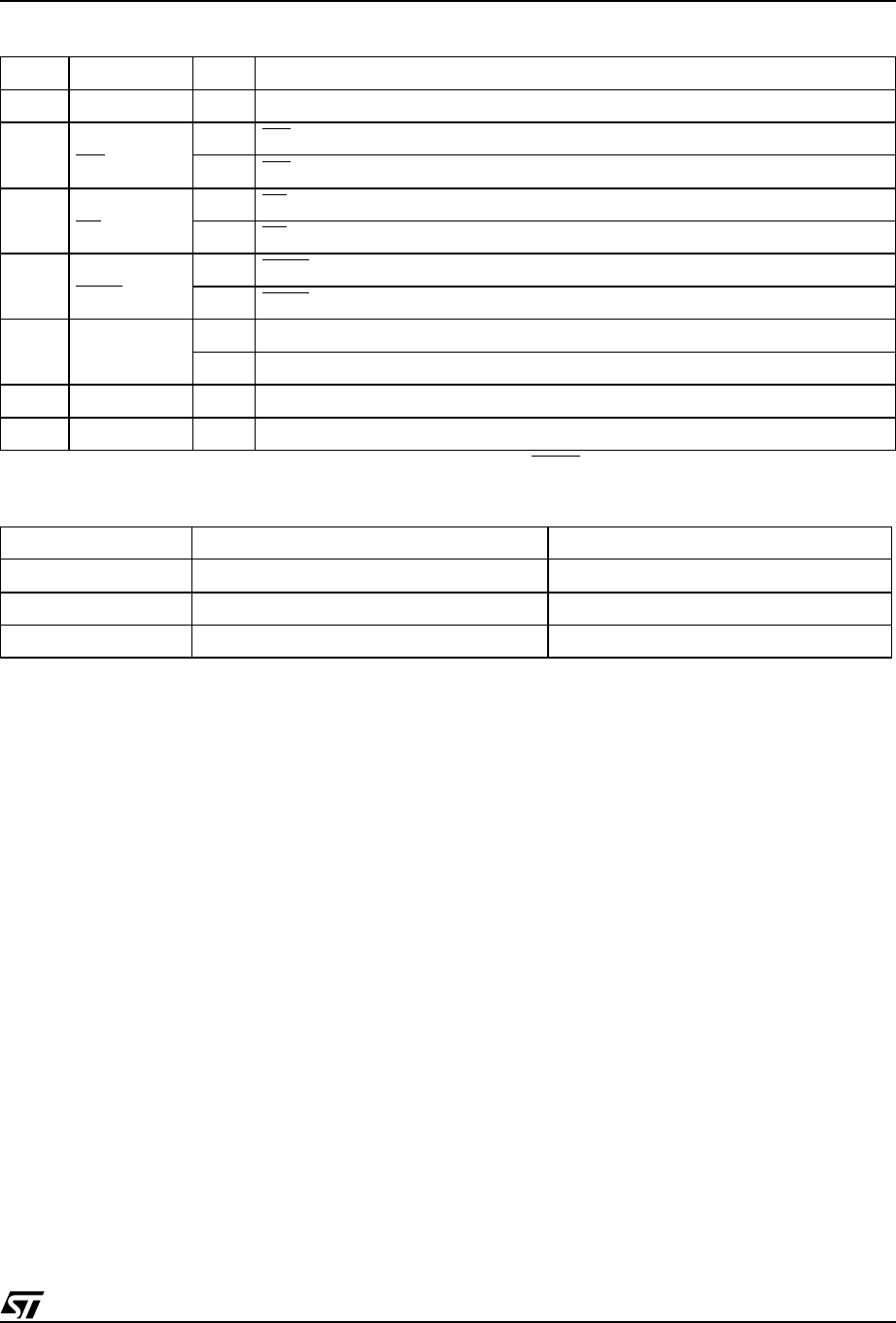
Table 100. Power Management Mode Registers PMMR2
Note: The bits of this register are cleared to zero following Power-up. Subsequent RESET pulses do not clear the registers.
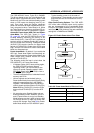
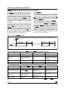
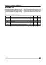
Table 101. APD Counter Operation
Bit 0 X 0 Not used, and should be set to zero.
Bit 1 X 0 Not used, and should be set to zero.
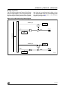
Bit 2
PLD Array
WR
0 = on WR input to the PLD AND Array is connected.
1 = off WR
input to PLD AND Array is disconnected, saving power.
Bit 3
PLD Array
RD
0 = on RD input to the PLD AND Array is connected.
1 = off RD
input to PLD AND Array is disconnected, saving power.
Bit 4
PLD Array
PSEN
0 = on PSEN input to the PLD AND Array is connected.
1 = off PSEN
input to PLD AND Array is disconnected, saving power.
Bit 5
PLD Array
ALE
0 = on ALE input to the PLD AND Array is connected.
1 = off ALE input to PLD AND Array is disconnected, saving power.
Bit 6 X 0 Not used, and should be set to zero.
Bit 7 X 0 Not used, and should be set to zero.
APD Enable Bit ALE Level APD Counter
0 X Not Counting
1 Pulsing Not Counting
1 0 or 1 Counting (Generates PDN after 15 Clocks)