


57/163
uPSD3212A, uPSD3212C, uPSD3212CV
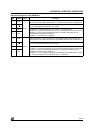
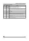
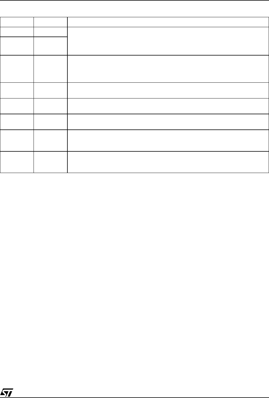
Table 44. Description of the SCON Bits
Bit Symbol Function
7 SM0 (SM1,SM0)=(0,0): Shift Register. Baud rate = f
OSC
/12
(SM1,SM0)=(1,0): 8-bit UART. Baud rate = variable
(SM1,SM0)=(0,1): 8-bit UART. Baud rate = f
OSC
/64 or f
OSC
/32
(SM1,SM0)=(1,1): 8-bit UART. Baud rate = variable
6SM1
5SM2
Enables the multiprocessor communication features in Mode 2 and 3. In Mode 2 or 3, if
SM2 is set to '1,' RI will not be activated if its received 8th data bit (RB8) is '0.' In Mode 1,
if SM2=1, RI will not be activated if a valid Stop Bit was not received. In Mode 0, SM2
should be '0'
4REN
Enables serial reception. Set by software to enable reception. Clear by software to
disable reception
3TB8
The 8th data bit that will be transmitted in Modes 2 and 3. Set or clear by software as
desired
2RB8
In Modes 2 and 3, this bit contains the 8th data bit that was received. In Mode 1, if
SM2=0, RB8 is the Snap Bit that was received. In Mode 0, RB8 is not used
1TI
Transmit Interrupt Flag. Set by hardware at the end of the 8th bit time in Mode 0, or at
the beginning of the Stop Bit in the other modes, in any serial transmission. Must be
cleared by software
0RI
Receive Interrupt Flag. Set by hardware at the end of the 8th bit time in Mode 0, or
halfway through the Stop Bit in the other modes, in any serial reception (except for
SM2). Must be cleared by software