


75/163
uPSD3212A, uPSD3212C, uPSD3212CV
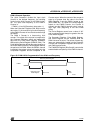
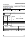
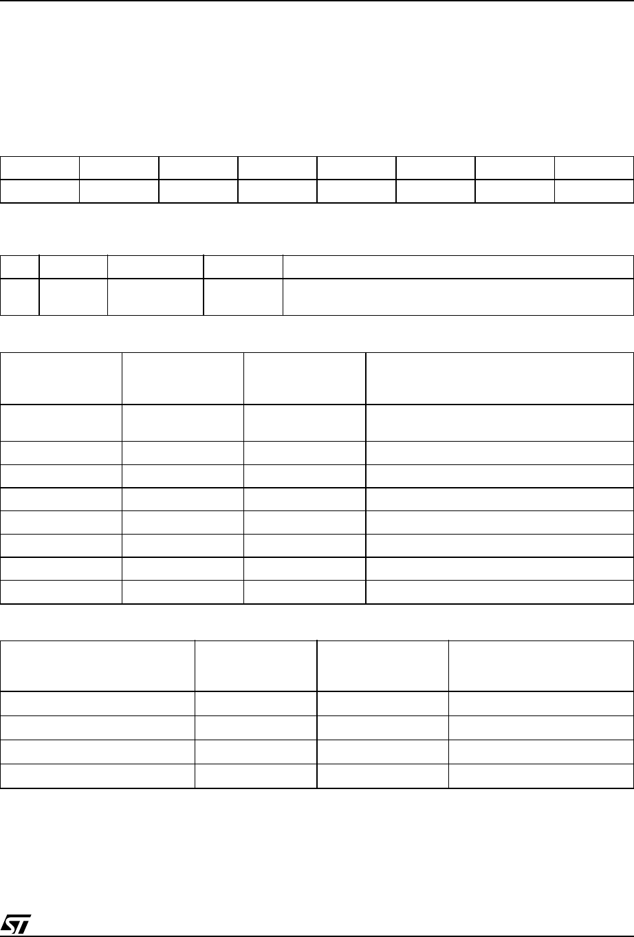
Address Register (S2ADR)
This 8-bit register may be loaded with the 7-bit
slave address to which the controller will respond
when programmed as a slave receive/transmitter.
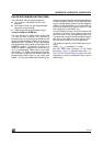
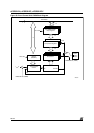
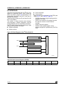
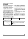
The Start/Stop Hold Time Detection and System
Clock registers (Tables 57 and 58) are included in
the I
2
C unit to specify the start/stop detection time
to work with the large range of MCU frequency val-
ues supported. For example, with a system clock
of 40MHz.
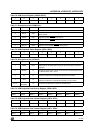
Table 56. Address Register (S2ADR)
Note: SLA6 to SLA0: Own slave address.
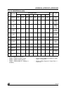
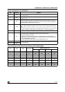
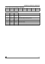
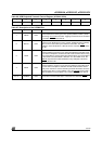
Table 57. Start /Stop Hold Time Detection Register (S2SETUP)
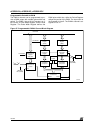
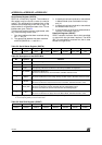
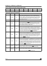
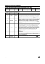
Table 58. System Cock of 40MHz
Table 59. System Clock Setup Examples
76543210
SLA6 SLA5 SLA4 SLA3 SLA2 SLA1 SLA0 —
Address Register Name Reset Value Note
SFR D2h S2SETUP 00h
To control the start/stop hold time detection for the multi-master
I²C module in Slave Mode
S1SETUP,
S2SETUP Register
Value
Number of Sample
Clock (f
OSC
/2 – >
50ns)
Required Start/
Stop Hold Time
Note
00h 1EA 50ns
When Bit 7 (enable bit) = 0, the number of
sample clock is 1EA (ignore Bit 6 to Bit 0)
80h 1EA 50ns
81h 2EA 100ns
82h 3EA 150ns
... ... ...
8Bh 12EA 600ns Fast Mode I²C Start/Stop hold time specification
... ... ...
FFh 128EA 6000ns
System Clock
S1SETUP,
S2SETUP Register
Value
Number of Sample
Clock
Required Start/Stop Hold Time
40MHz (f
OSC
/2 – > 50ns)
8Bh 12 EA 600ns
30MHz (f
OSC
/2 – > 66.6ns)
89h 9 EA 600ns
20MHz (f
OSC
/2 – > 100ns)
86h 6 EA 600ns
8MHz (f
OSC
/2 – > 250ns)
83h 3 EA 750ns