


63/163
uPSD3212A, uPSD3212C, uPSD3212CV
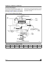
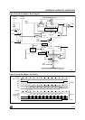
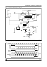
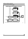
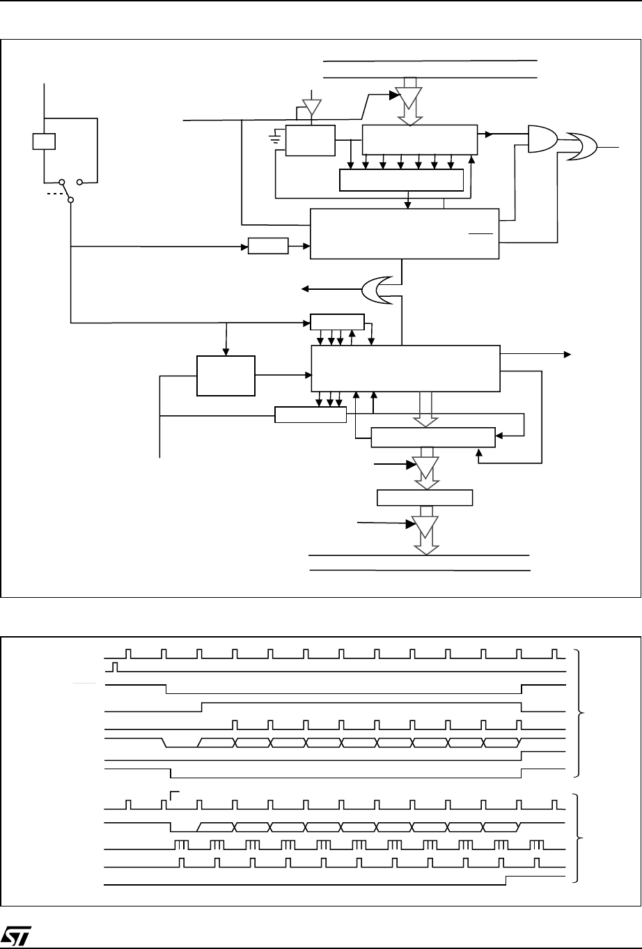
Figure 31. Serial Port Mode 2, Block Diagram
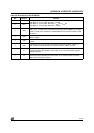
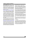
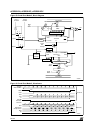
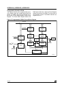
Figure 32. Serial Port Mode 2, Waveforms
AI06844
Zero Detector
Internal Bus
Tx Control
Rx Control
Internal Bus
SBUF
Write
to
SBUF
Read
SBUF
Load
SBUF
SBUF
Input Shift Register
Shift
Serial
Port
Interrupt
Rx Clock
Start
Tx Clock
Start
Shift
Shift
Send
Load SBUF
TI
RI
CL
DS
Q
1FFh
TxD
Data
Rx Detector
RxD
1-to-0
Transition
Detector
÷16
Sample
÷16
÷2
TB8
Phase2 Clock
1/2*f
OSC
01
SMOD
AI06845
Write to SBUF
Data
Shift
TxD
TI
Rx Clock
RxD
Bit Detector
Sample Times
Shift
RI
S1P1
÷16 Reset
Receive
Transmit
D0 D1 D2 D3 D4 D5 D6 D7
Send
Tx Clock
Start Bit
Stop Bit
TB8
D0 D1 D2 D3 D4 D5 D6 D7
Start Bit
Stop Bit
RB8
Stop Bit
Generator