


33/163
uPSD3212A, uPSD3212C, uPSD3212CV
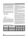
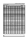
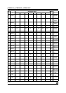
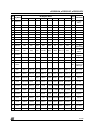
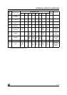
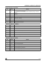
Note: (Register address = csiop address + address offset; where csiop address is defined by user in PSDsoft)
* indicates bit is not used and need to set to '0.'
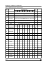
21
Output
Macrocells BC
22
Mask Macrocells
AB
23
Mask Macrocells
BC
C0
Primary Flash
Protection
Sec3_
Prot
Sec2_
Prot
Sec1_
Prot
Sec0_
Prot
Bit = 1 sector
is protected
C2
Secondary Flash
Protection
Security
_Bit
*****
Sec1_
Prot
Sec0_
Prot
Security Bit =
1 device is
secured
B0 PMMR0 * *
PLD
Mcells
clk
PLD
array-
clk
PLD
Turbo
*
APD
enable
*00
Control PLD
power
consumption
B4 PMMR2 *
PLD
array
Ale
PLD
array
Cntl2
PLD
array
Cntl1
PLD
array
Cntl0
**00
Blocking
inputs to PLD
array
E0 Page 00 Page Register
E2 VM
Periph-
mode
**
FL_
data
Boot_
data
FL_
code
Boot_
code
SR_
code
Configure
8032 Program
and Data
Space
CSIOP
Addr
Offset
Register Name
Bit Register Name
Reset
Value
Comments
76543210