


49/163
uPSD3212A, uPSD3212C, uPSD3212CV
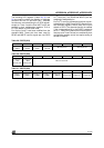
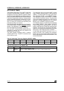
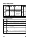
Table 39. Description of the TMOD Bits
Bit Symbol Timer Function
7Gate
Timer 1
Gating control when set. Timer/Counter 1 is enabled only while INT1 pin is High and
TR1 control pin is set. When cleared, Timer 1 is enabled whenever TR1 control bit is set
6C/T
Timer or Counter selector, cleared for timer operation (input from internal system clock);
set for counter operation (input from T1 input pin)
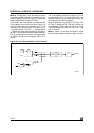
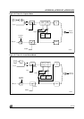
5 M1 (M1,M0)=(0,0): 13-bit Timer/Counter, TH1, with TL1 as 5-bit prescaler
(M1,M0)=(0,1): 16-bit Timer/Counter. TH1 and TL1 are cascaded. There is no prescaler.
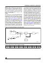
(M1,M0)=(1,0): 8-bit auto-reload Timer/Counter. TH1 holds a value which is to be
reloaded into TL1 each time it overflows
(M1,M0)=(1,1): Timer/Counter 1 stopped
4M0
3Gate
Timer 0
Gating control when set. Timer/Counter 0 is enabled only while INT0 pin is High and
TR0 control pin is set. When cleared, Timer 0 is enabled whenever TR0 control bit is set
2C/T
Timer or Counter selector, cleared for timer operation (input from internal system clock);
set for counter operation (input from T0 input pin)
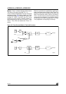
1 M1 (M1,M0)=(0,0): 13-bit Timer/Counter, TH0, with TL0 as 5-bit prescaler
(M1,M0)=(0,1): 16-bit Timer/Counter. TH0 and TL0 are cascaded. There is no prescaler.
(M1,M0)=(1,0): 8-bit auto-reload Timer/Counter. TH0 holds a value which is to be
reloaded into TL0 each time it overflows
(M1,M0)=(1,1): TL0 is an 8-bit Timer/Counter controlled by the standard TImer 0 control
bits. TH0 is an 8-bit timer only controlled by Timer 1 control bits
0M0