


– 6 –
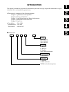
SPECIFICATIONS AND OPERATION
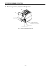
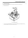
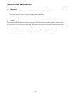
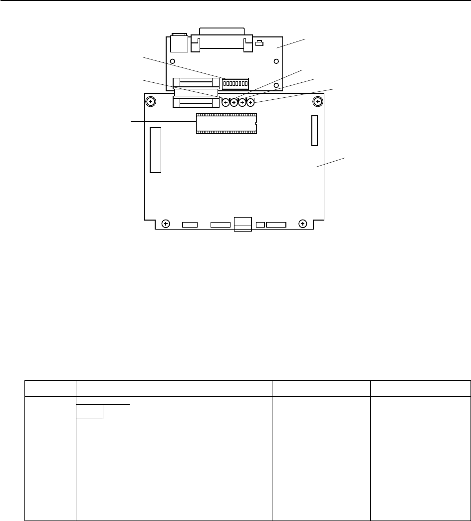
Fig. 1-4 Main and interface PCBs
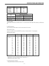
3 Set the DIP switches on the interface PCB.
2. DIP-switch values
1 RS232C interface
This board has a single 8-bit DIP switch. Switch settings are as follows.
Switch Setting ON OFF
1-1 Baud
1-2
1-3 Handshaking DTR XON/XOFF
1-4 Data length 8 bits 7 bits
1-5 Parity use No parity Parity used
1-6 Parity type Odd Even
1-7 DC1/DC3 Ineffective Effective
1-8 Status of printer power
* All of these are set to ON before the printer is shipped from the factory.
Opening under ROM cover
EPROM
VP4 (Black-mark sensor)
VR1 (Transmissive sensor -
coarse)
DIP switches
Interface PCB (RS232C)
VR3 (Paper-out sensor)
VR2 (Transmissive sensor - fine)
Main PCB