


– 22 –
THEORY OF OPERATION
D2O
D1O
D2EN
D2I
D1EN
D1I
ERROR
ACK
RD (+)
RD (–)
CS (+)
CS (–)
RS (–)
RS (+)
SD (–)
SD (+)
CN3 CN1
IC1
+
–
+
–
Gate array
CN9 IC10
R2I
+
R2I
–
R1I
+
R1I
–
D2O
D2O
D1O
D1O
RXD0
TXD0
RXD1
CPU
IC5
A15
B15
A10
B12
B14
A15
B15
A10
B12
B14
MC34051
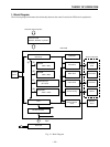
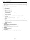
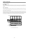
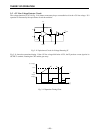
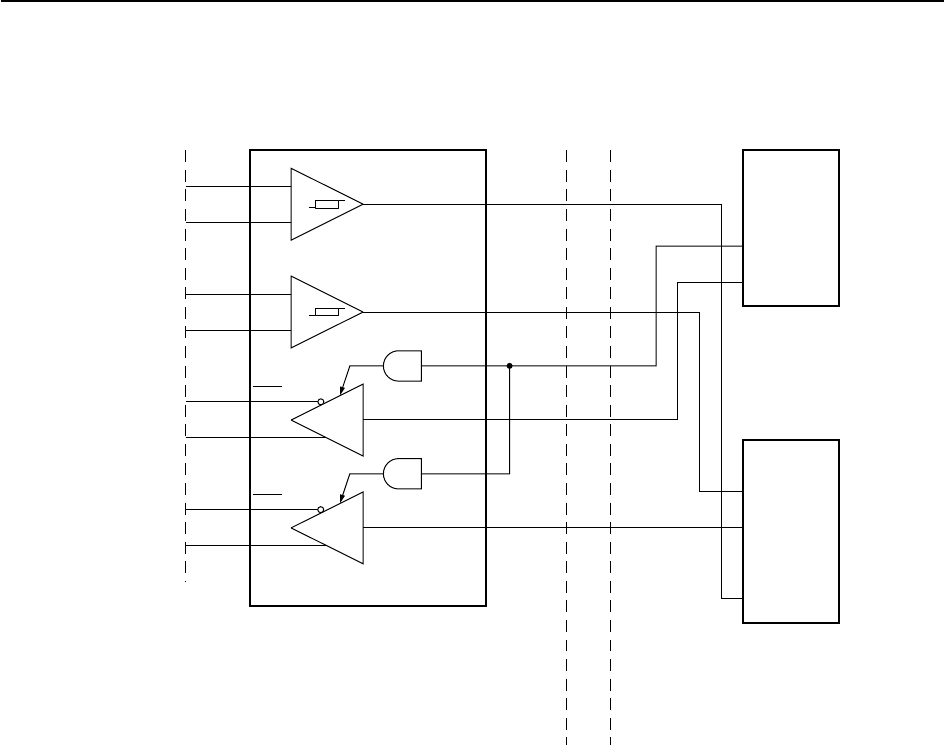
2-1-2. RS422A interface
RS422A Interface PCB Main PCB
Fig. 2-3 RS422A Interface
IC1 operates as the RS422A driver and receiver.
Data flow from host to printer: IC1 receives serial data from the host computer via RD, converts the signal voltage from
RS422A level to TTL level, and passes the result to the CPU. The CPU converts the serial data to parallel and stores it
into buffer memory.
Data flow from printer to host: The CPU generates data, converts it into serial form, then passes it to IC1. IC1 converts
the signal voltage from TTL level to RS422A level, then outputs the result over the SD line.
The CS line is hardware-connected, but the connection is not recognized by software. (The printer does not monitor the
signal.)