


– 10 –
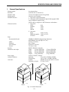
SPECIFICATIONS AND OPERATION
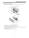
Sensor adjustment procedures are as follows.
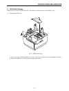
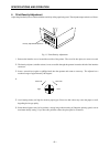
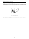
1) Remove the ROM cover, located beneath the paper-roll holding area.
2) Hold down the FEED and ON LINE buttons while switching on the power, and continue to hold them down until
you hear a triple beep. (This will take about five seconds.) When you hear the triple beep, release the buttons to
enter sensor-adjustment mode.
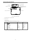
a) Reflective Sensor
• Insert a non-black area of paper into the mechanism’s sensor area.
• Rotate the main PCB’s reflective-sensor adjustment knob (VR4) to the point where the Head Up LED comes
on.
b) Paper-Out Sensor
• Insert a non-black area of paper into the mechanism’s sensor area.
• Rotate the main PCB’s paper-out-sensor adjustment knob (VR3) to the point where the Paper End LED switches
on.
c) Transmissive Sensor
• Insert the backing portion of a label sheet into the mechanism’s transmissive sensor area. (Insert the backing
part only, not the label itself.)
• Adjust the main PCB’s coarse (VR1) and fine (VR2) transmissive-sensor adjustment knobs to the point where
the Error LED comes on.
Note: When setting paper, be sure to lower the head so that it is close to its normal fixed position.
After the sensor has been adjusted, press the ON LINE switch to exit the sensor adjustment mode and return to the
normal operation mode.