


– 26 –
THEORY OF OPERATION
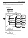
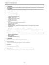
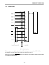
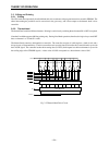
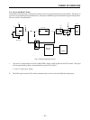
2-3. Feed-Motor Drive Circuit
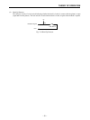
The printer employs a 4-phase step motor (phase 1-2 excitation) to implement paper feed. The motor rotates through a
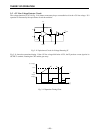
certain angle each time it receives a pulse from the drive circuit. The following diagram illustrates the phase 1-2 excitation
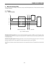
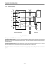
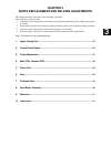
method. Diagram 2-8 shows the feed-motor drive circuit.
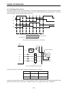
Fig. 2-8 Motor Control by Phase 1-2 Excitation
Fig. 2-9 Feed-Motor Drive Circuit
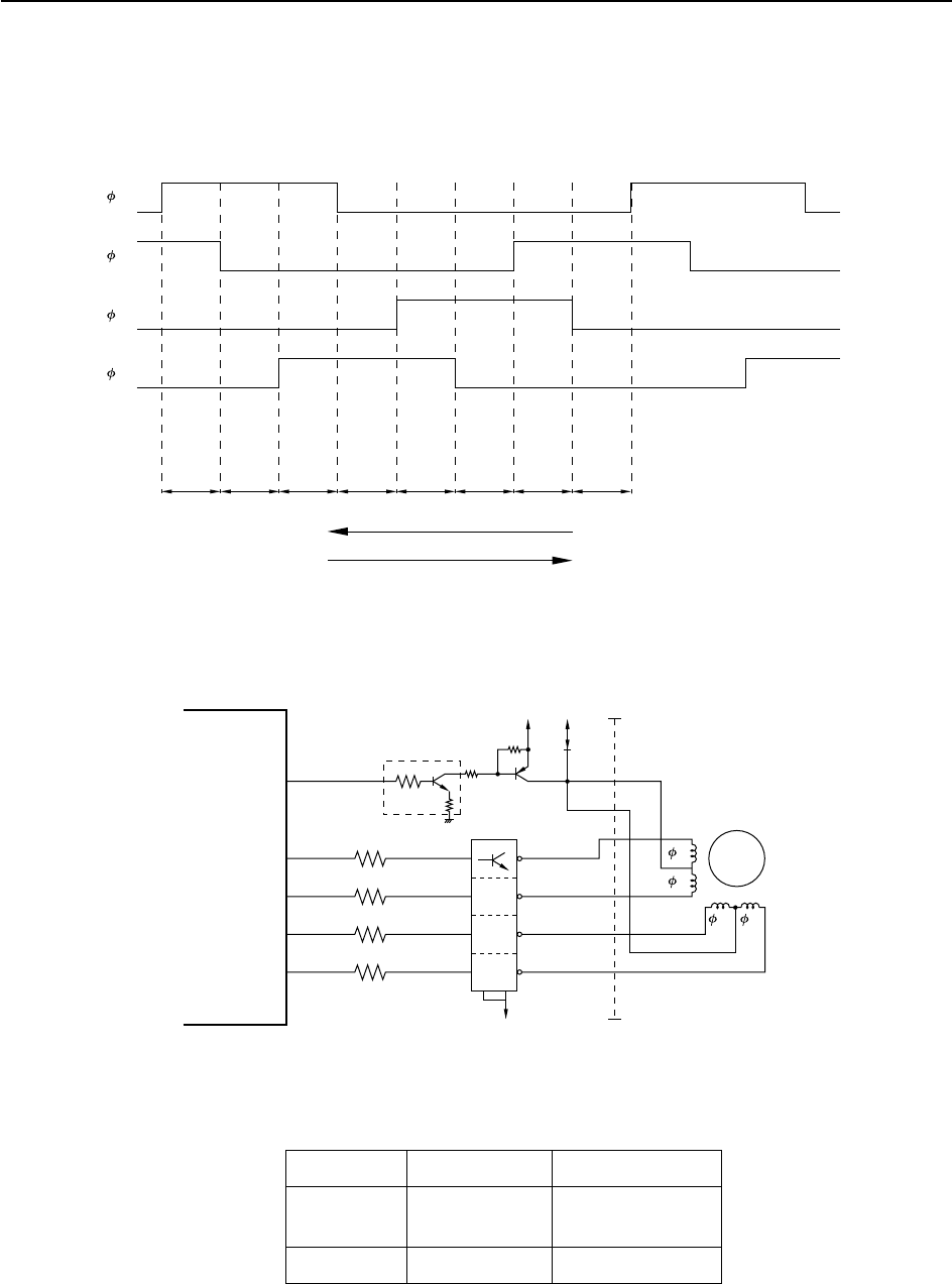
Voltage to the motor is controlled to produced the required action, as follows.
Mode Voltage Action
Operating VM (+24V) Drives the motor
VL (+5V)
Idle VL (+5V) Holds the motor
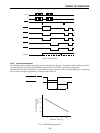
Voltage is controlled by PA4 of the CPU, which goes HIGH or LOW to switch transistors DQ2 and Q2 ON or OFF. When
Q2 is ON, the motor receives +24V (VM). When Q2 is OFF, +5V is supplied to the motor via diode D1.
1 2 3 4 5 6 7 8
1
2
3
4
ON
ON
ON
ON
ON
Step
PA4
PA0
PA2
PA3
PA1
1
2
3
4
CN4
1
2
4
5
6
3
M
+5V+24V
Q2
D1
TA1
B
DQ2
M-GND
E
IC5
CPU
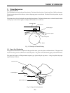
Paper-feed motor
Forward Feed
Reverse Feed