


– 25 –
THEORY OF OPERATION
24V
t
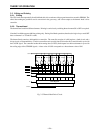
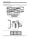
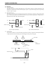
CLOCK
SI
LATCH
STROBE1
STROBE2
STROBE3
STROBE4
STROBE5
COMMON
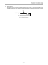
STROBE1, STROBE2, STROBE3
STROBE4, STROBE5,
t t
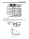
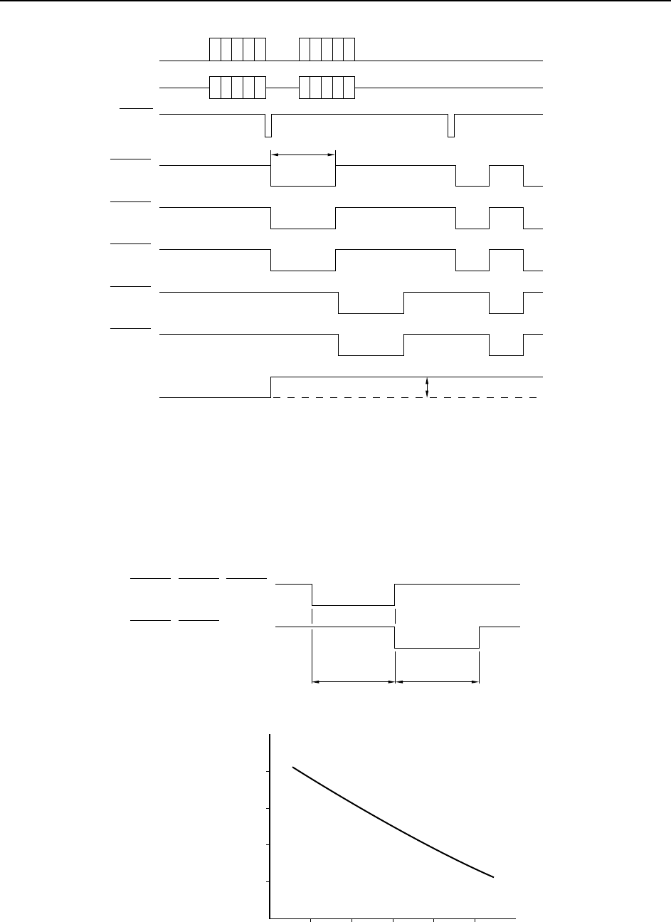
10 20 30 40 50
300
400
500
Head Energizing Time
t (µsec)
Thermistor Temp. (°C)
600
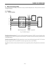
Fig.2-6 Timing Chart
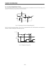
2-2-3. Head current control
Heat buildup in the head during operation can cause print quality to degrade. To maintain uniform quality, the printer
varies the energizing time (time that STROBE remains LOW) in accordance with the head temperature.
The thermal head’s surface temperature is calculated based on the resistance value of an attached thermistor. Energizing
time is reduced at higher temperatures, as indicated in the figure 2-6.
Fig. 2-7 Head Energizing Control