


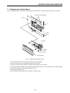


– 19 –
THEORY OF OPERATION
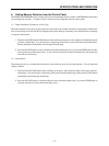
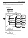
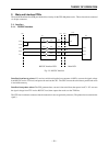
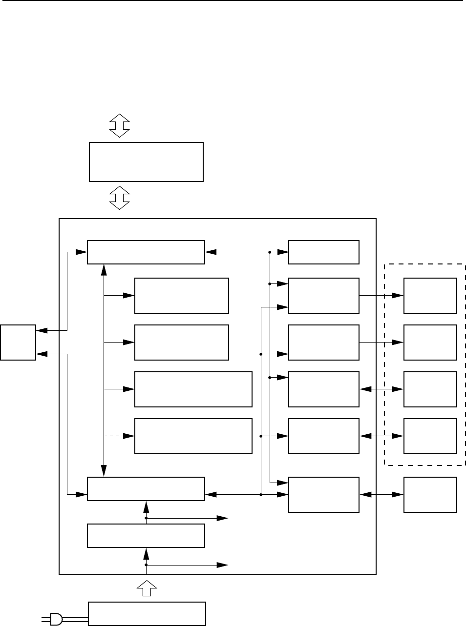
1. Block Diagram
The following diagram illustrates the relationship between the control board (main PCB) and its peripherals.
(16)
(16)
(8)
(8)
(16)
24V
Data flow (Host computer)
Control
panel
Main PCB
Gate array
CPU
DC-DC converter
Power unit
EPROM
128K × 16bits
PS-RAM
128K × 16bits
S-RAM (backup)
8K × 8 bits
Kanji ROM
256K × 16 bits
EEPROM
Head driver
Motor driver
Cutter driver
Sensor circuitry
External device
driver
Thermal
head
Printer mechanism
Feed motor
Autocutter
Sensor
External
device
Interface board
RS232C, RS422A, or parallel
Fig. 2-1 Block Diagram