


– 27 –
THEORY OF OPERATION
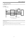
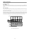
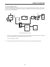
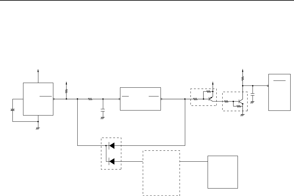
2-4. Power-On Reset Circuit
Immediately following power-on the printer executes a power-on reset, initializing all circuit elements. The power-on
reset serves as protection against operational errors. The power-on RESET signal is maintained for approximately 160ms.
The reset circuit is illustrated below.
Fig. 2-10 Power-On Reset Circuit
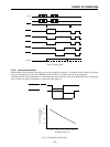
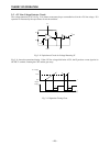
1 At power on, voltage-detector circuit IC4 (M51953BL) outputs a LOW signal from its OUT terminal. The signal
lasts for approximately 160ms, as determined by capacitor C2 (0.47µF):
T = 0.34 × C2 (pF) [µs] = 160ms
2 The LOW signal resets the CPU and the mechanism drive circuits, and sets S-RAM into backup state.
+5V
IC4
CD
C2
GND
+5V
+5V
+5V
VCC
RESET
DD3
IC5 : CPU
RES
RESO
RESET
VCC
S-RAM
+
Gate
array
IC1
RESET IC
IC10
Back-up
Circuit
CPU