


PARTS REPLACEMENT
– 39 –
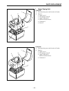
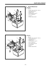
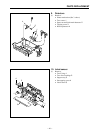
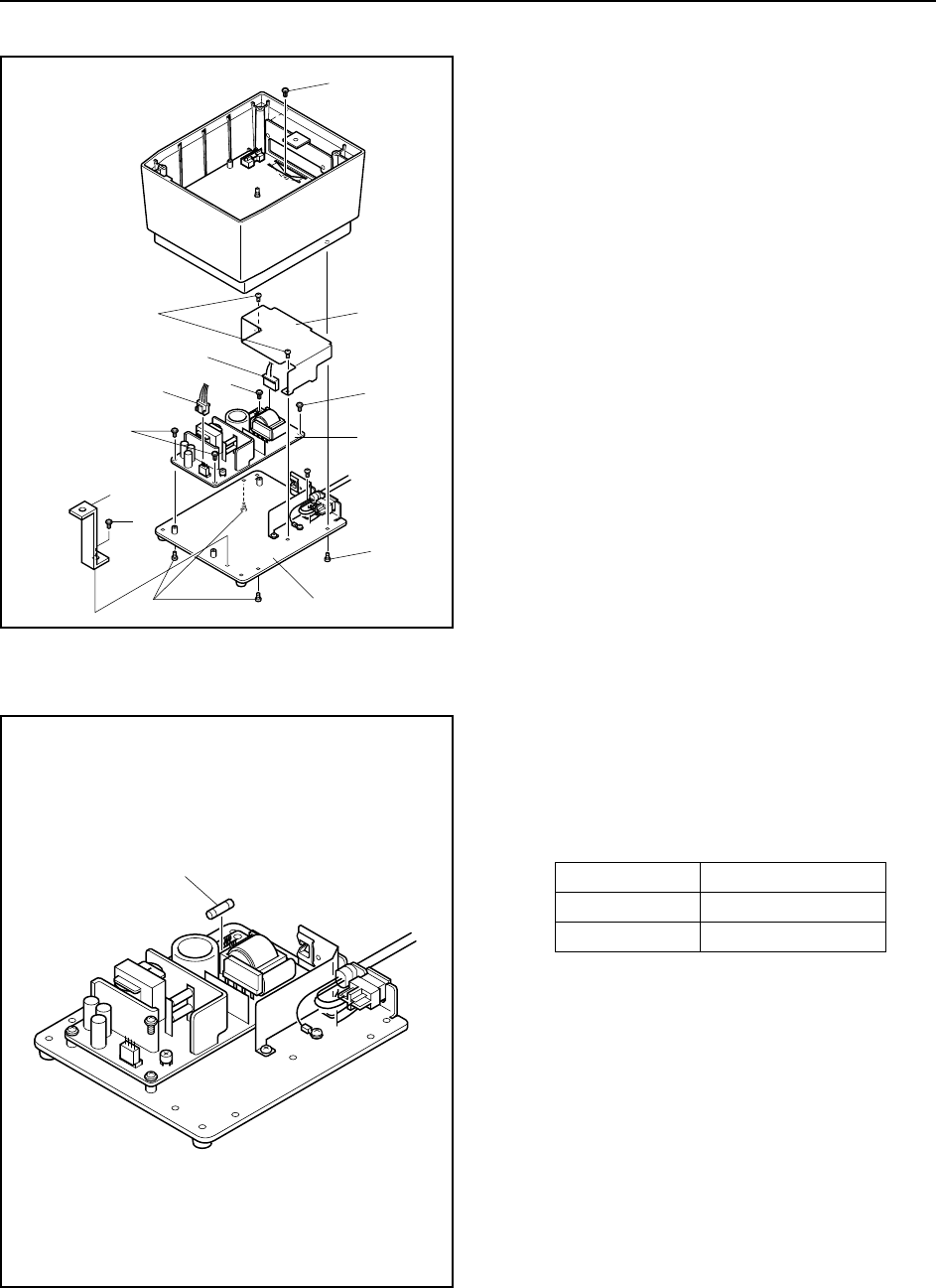
5. Power Unit
(1) Disconnect the power cord from the AC outlet.
(2) Remove:
• Upper casing unit (See 1. above.)
• Three screws (See 4. above.)
• Interface PCB (See 4. above.)
• Screw 1
• Four screws 2
• Lower casing chassis 3
• Connector 4
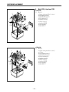
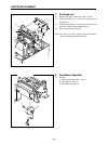
• Two tapping screws 5
• Shield chassis (A) 6
• Connector 7
• Four screws 8
• Power unit 9
• Screw 0
• Earth plate (A) A
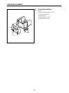
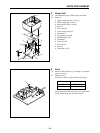
6. Fuse
(1) Remove shield chassis A, according to procedure
given in 5. above.
(2) Check fuse F1. 1
If the fuse is blown, replace with the following.
AC Voltage F1
120V 5TT5A-125V
220-240V EAK3.15A250V
If the replacement fuse also blows out, replace the
power unit or check the main logic board.
6
8
2
1
9
8
7
8
5
4
3
2
0
A
1