


– 5 –
SPECIFICATIONS AND OPERATION
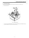
3. DIP-Switch Settings
DIP switches are located on the interface PCB. The number of switches depends on the interface type.
(1) Setting the DIP Switches
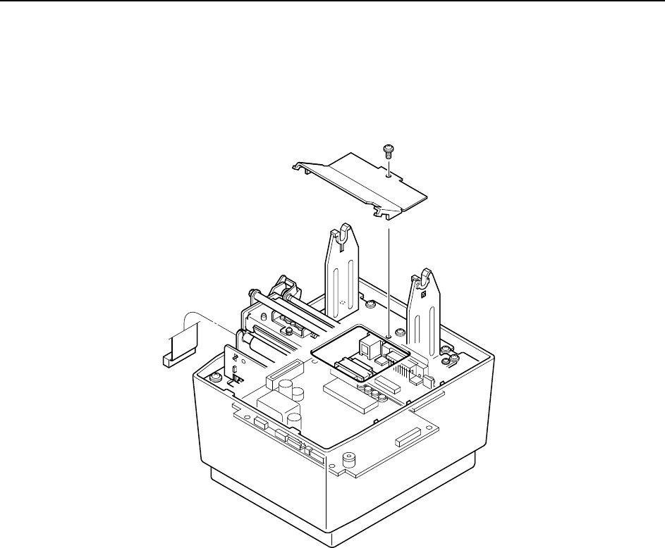
Fig. 1-3 DIP-Switch Settings
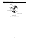
1 Remove the screw holding the ROM cover in place. (The screw is located at the base of the paper-roll holder.)
2 Remove the ROM cover, exposing the main and interface PCBs.