


– 28 –
THEORY OF OPERATION
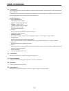
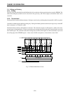
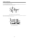
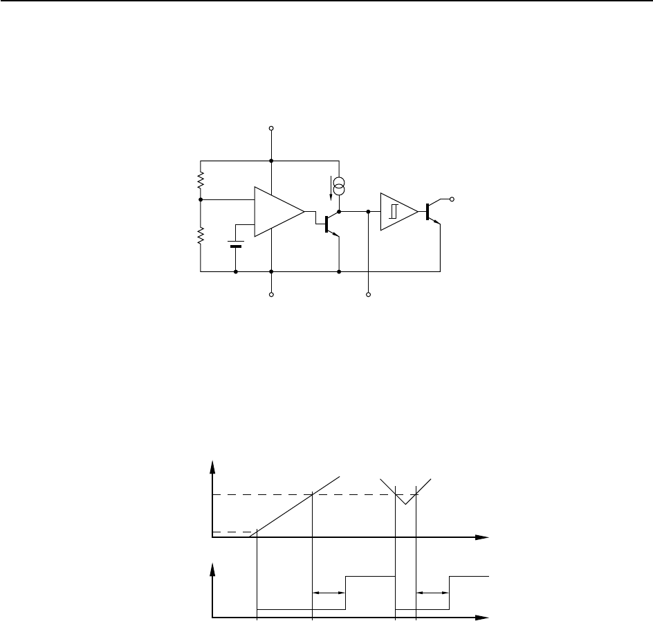
2-5. +5V Line Voltage Detector Circuit
The voltage-detection IC (IC4 in Fig. 2-10) detects momentary drops or unstable levels in the +5V line voltage. IC4
operation is illustrated by the equivalence circuit shown below.
Fig. 2-11 Equivalence Circuit for Voltage Detecting IC
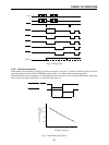
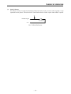
Fig. 2-11 shows the operational timing. If the +5V line voltage falls below 4.25V, the IC produces a reset signal at its
OUTPUT terminal, resetting the CPU and the gate array.
Fig. 2-12 Operation Timing Chart
1.25V
R1
R2
SµA typ
V
CC
1
GND
3
Cd
4
–
OUT
5
–
+
VCC Voltage
4.25V
0.8V
Output
Voltage
tdtd
t
t
td = 0.34 × Cd (pF) [µs]