


– 20 –
THEORY OF OPERATION
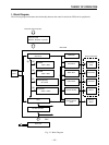
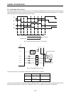
1. 1 Control board
The interface board relays data from the host computer to the main board. The main board’s CPU stores the data
into local RAM.
It then reads out the data, edits it according to the control program stored in the board’s ROM, and prints the results
by issuing appropriate drive signals to the printer mechanism.
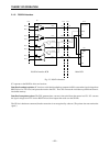
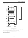
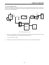
[Block Description]
a. CPU: HD641300F10T
CMOS single-chip computer
Controls overall printer operation.
b. EPROM: 128 K × 16 bits
Contains the CPU control program.
c. PS-RAM: 128 K × 16 bits
Work area and data buffer
d. S-RAM
Saves format data and externally defined characters.
Backed up by super capacitor.
e. EEPROM: 1024 bits
Stores printer settings. Settings can be changed by software. (Used in place of dip-switches.)
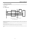
f. Interface board
Interfaces the main board with the host computer.
There are three versions, each for a different interface type: RS232C, RS422A, or Centronics parallel.
g. Gate array
Executes various types of signal processing.
h. Drivers
The various drivers convert signals received from the CPU and gate array into the drive signals that directly
control the printer mechanism.
i. DC-DC converter
Converts the supplied 24V to 5V.
1. 2 Control Panel
Provides manual control switches and operational indicators.
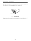
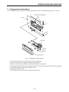
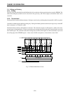
1. 3 Printer mechanism
Comprised of thermal head, paper-feed motor, and sensor mechanism.
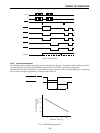
1. 4 Power unit
Converts primary power to DC24V.
1. 5 External device
External device (such as cash drawer) driven by signals issued by the control board.